Chopper-stabilized instrumentation amplifier

a technology of instrumentation amplifiers and stabilizers, which is applied in the field of amplifiers, can solve the problems of large ripple in the passband, the chopper-stabilized architecture may have a limited bandwidth, and the accuracy of measurement signals are undermining, so as to eliminate noise and offset, stable measurements, and low power

Active Publication Date: 2011-03-24
MEDTRONIC INC
View PDF99 Cites 27 Cited by
  • Summary
  • Abstract
  • Description
  • Claims
  • Application Information

AI Technical Summary

Benefits of technology

This disclosure describes a chopper stabilized instrumentation amplifier. The instrumentation amplifier is configured to achieve stable measurements at low frequency with very low power. The instrumentation amplifier uses a differential architecture and a mixer amplifier to substantially eliminate noise and offset from an output signal produced by the amplifier. Dynamic limitations, i.e., glitching, that result from chopper stabilization at low power are substantially eliminated or reduced through a combination of chopping at low impedance nodes within the mixer amplifier and feedback. The signal path of the instrumentation amplifier operates as a continuous time system, providing minimal aliasing of noise or external signals entering the signal pathway at the chop frequency or its harmonics. In this manner, the instrumentation amplifier can be used in a low power system, such as an implantable medical device, to provide a stable, low-noise output signal.

Problems solved by technology

However, a discrete time architecture can produce undesirable aliasing of noise and signals, undermining the accuracy of measurement signals.
A chopper-stabilized architecture may have a limited bandwidth, however, producing a large ripple in the passband.
The ripple may make implementation of chopper-stabilized designs difficult in low power applications.

Method used


Image

  • Chopper-stabilized instrumentation amplifier
  • Chopper-stabilized instrumentation amplifier
  • Chopper-stabilized instrumentation amplifier

Examples


Embodiment Construction

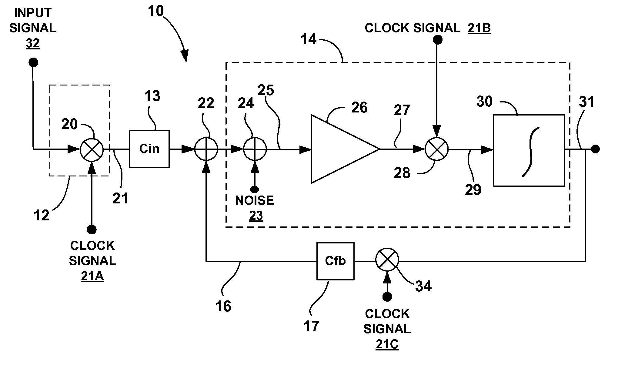
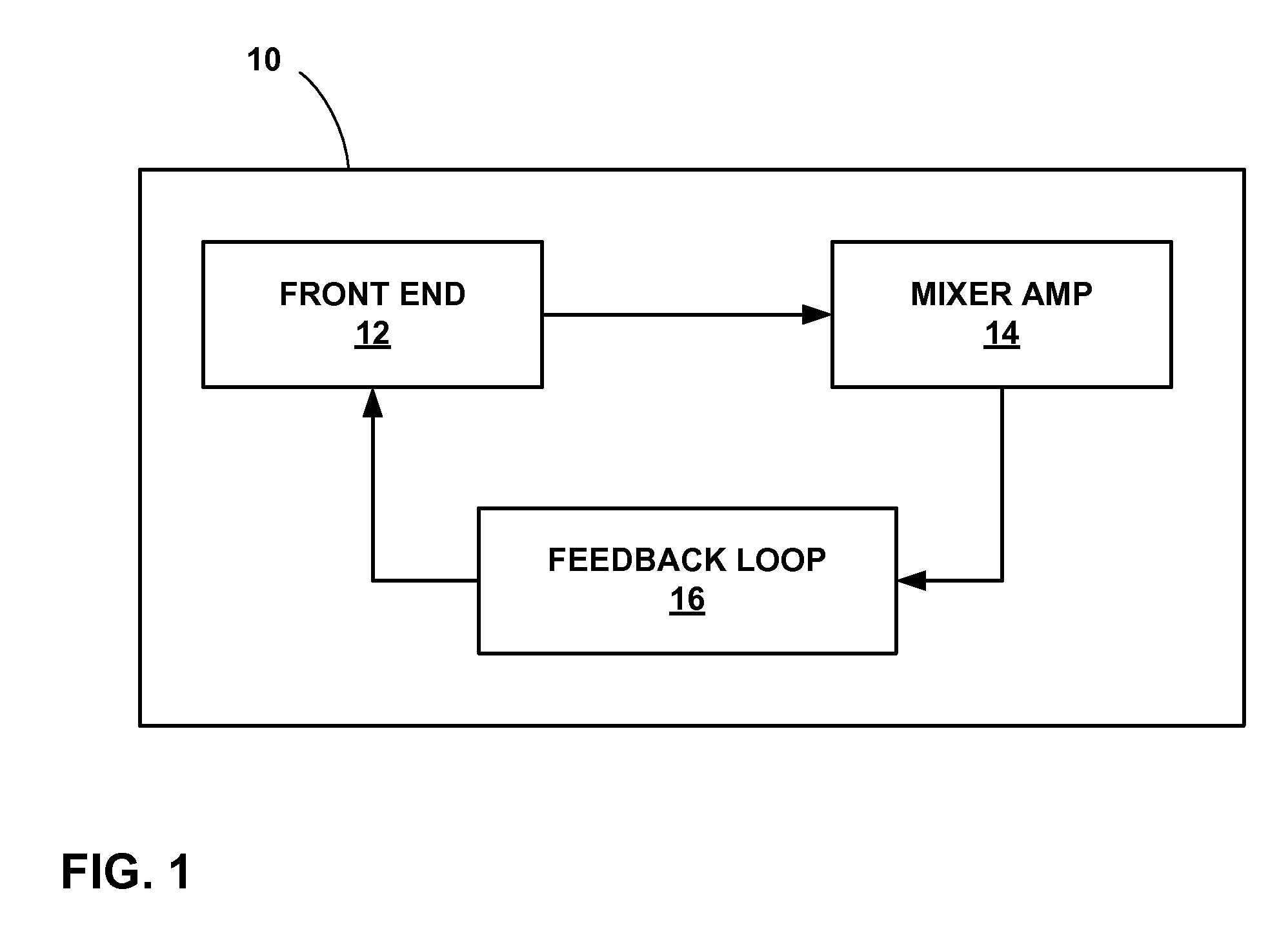
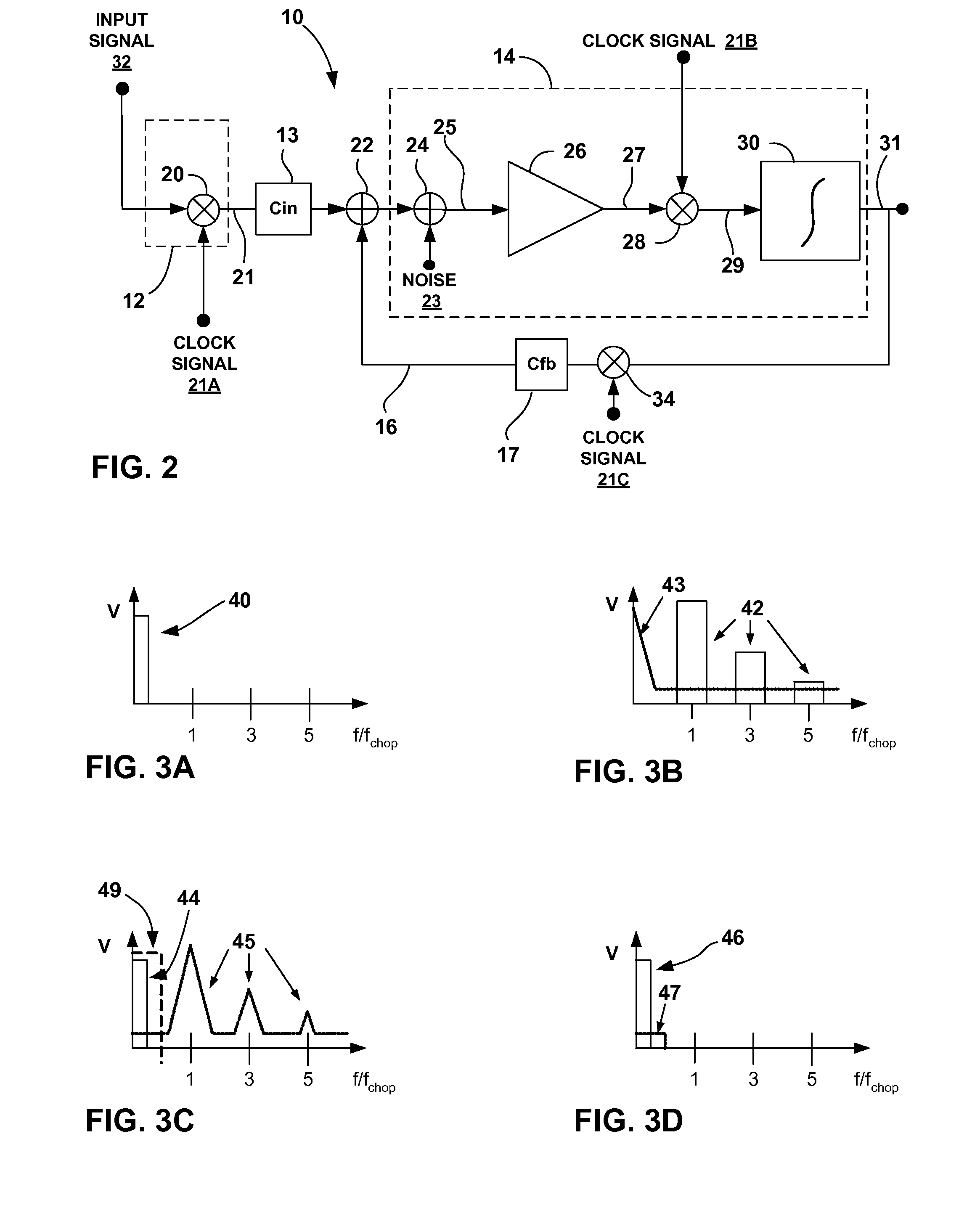
This disclosure describes a chopper-stabilized instrumentation amplifier. The instrumentation amplifier is configured to achieve stable measurements at low frequency with very low power. The instrumentation amplifier uses a differential architecture and a mixer amplifier to substantially eliminate noise and offset from an output signal produced by the amplifier. Dynamic limitations, i.e., glitching, that result from chopper stabilization at low power are substantially eliminated through a combination of chopping at low impedance nodes within the mixer amplifier and feedback. The signal path of the instrumentation amplifier operates as a continuous time system, providing minimal aliasing of noise or external signals entering the signal pathway at the chop frequency or its harmonics. In this manner, the instrumentation amplifier can be used in a low power system, such as an implantable medical device, to provide a stable, low-noise output signal.

The chopper-stabilized instrumentation ...


PUM


Abstract

This disclosure describes a chopper stabilized instrumentation amplifier. The amplifier is configured to achieve stable measurements at low frequency with very low power consumption. The instrumentation amplifier uses a differential architecture and a mixer amplifier to substantially eliminate noise and offset from an output signal produced by the amplifier. Dynamic limitations, i.e., glitching, that result from chopper stabilization at low power are substantially eliminated through a combination of chopping at low impedance nodes within the mixer amplifier and feedback. The signal path of the amplifier operates as a continuous time system, providing minimal aliasing of noise or external signals entering the signal pathway at the chop frequency or its harmonics. The amplifier can be used in a low power system, such as an implantable medical device, to provide a stable, low-noise output signal.

Description

TECHNICAL FIELDThe invention relates to amplifiers and, more particularly, to instrumentation amplifiers for accurate signal measurement.BACKGROUNDInstrumentation amplifiers are used to accurately measure a variety of test and measurement signals. A medical instrumentation amplifier, for example, may be configured to measure physiological signals, such as electrocardiogram (ECG), electromyogram (EMG), electroencephalogram (EEG), pressure, impedance, and motion signals. Typically, instrumentation amplifiers are constructed as differential amplifiers exhibiting low offset, low drift, low noise, high common mode rejection, high loop gain, and high input impedance. In many cases, instrumentation amplifiers may require careful matching and trimming of circuit components to achieve a high degree of accuracy.An instrumentation amplifier may be constructed with a discrete time switched capacitor architecture that obtains discrete signal samples. However, a discrete time architecture can pro...

Claims


Application Information

Patent Timeline
Patent Type & Authority Applications(United States)
IPC IPC(8): H03F3/38
CPCH03F3/38A61B5/04A61B5/053A61B5/7217A61B5/7242A61B5/7228A61B5/7203A61B5/7225A61B5/24
Inventor DENISON, TIMOTHY J.
Owner MEDTRONIC INC
Why Eureka
Try Eureka