Sensor Structure

a sensor and integrated technology, applied in the direction of electrical control, instruments, machines/engines, etc., can solve the problems of not being used for fuel control applications, various technical problems are expected to occur, and the humidity sensing device described above has not been used for fuel control, etc., to achieve accurate humidity sensing, reduce the total power consumption of the sensor, and improve the efficiency of heat radiation

Active Publication Date: 2011-03-31
HITACHI ASTEMO LTD
View PDF6 Cites 41 Cited by
  • Summary
  • Abstract
  • Description
  • Claims
  • Application Information

AI Technical Summary

Benefits of technology

[0020]Heat generated by the mass air flow measurement device is effectively utilized to remove condensed dew in the humidity sensing part. This eliminates the need to additionally provide a heater function around the humidity sensing part. Alternatively, condensed dew can be removed without the use of the heater function of the humidity sensing element. This enables accurate sensing of the humidity and a reduction in the total power consumption of the sensor.
[0021]Moreover, the improved efficiency of heat radiation, which is a cap...

Problems solved by technology

Furthermore, in that case a wire harness that interconnects various sensors and control devices as well as a control unit configured to control the sensors and control instruments is complicatedly intricate.
However, as heating resistor type mass air flow measurement devices are integrated with the above-described pressure sensing device and humidity sensing device in...

Method used


Image

  • Sensor Structure
  • Sensor Structure
  • Sensor Structure

Examples


Embodiment Construction

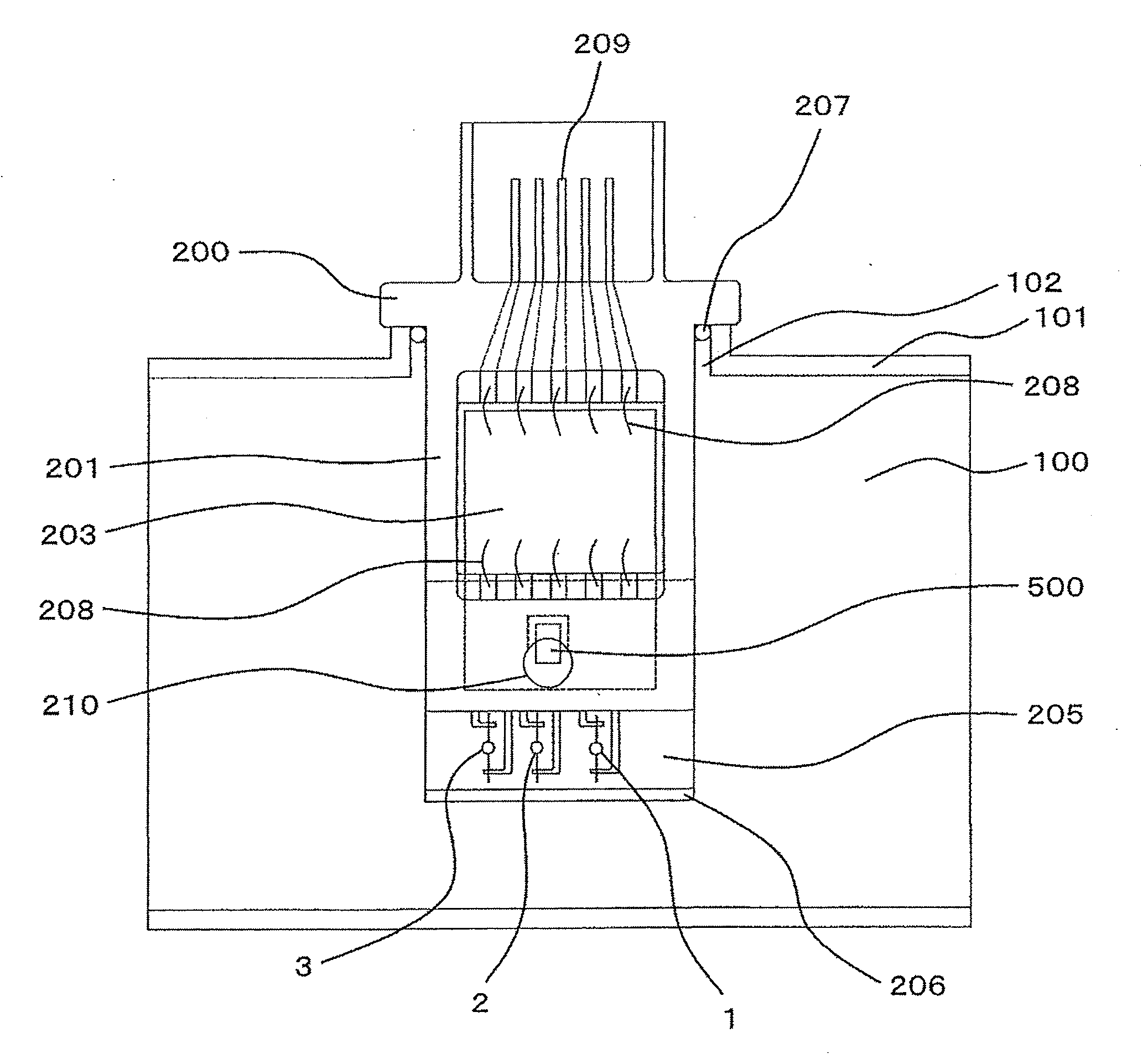
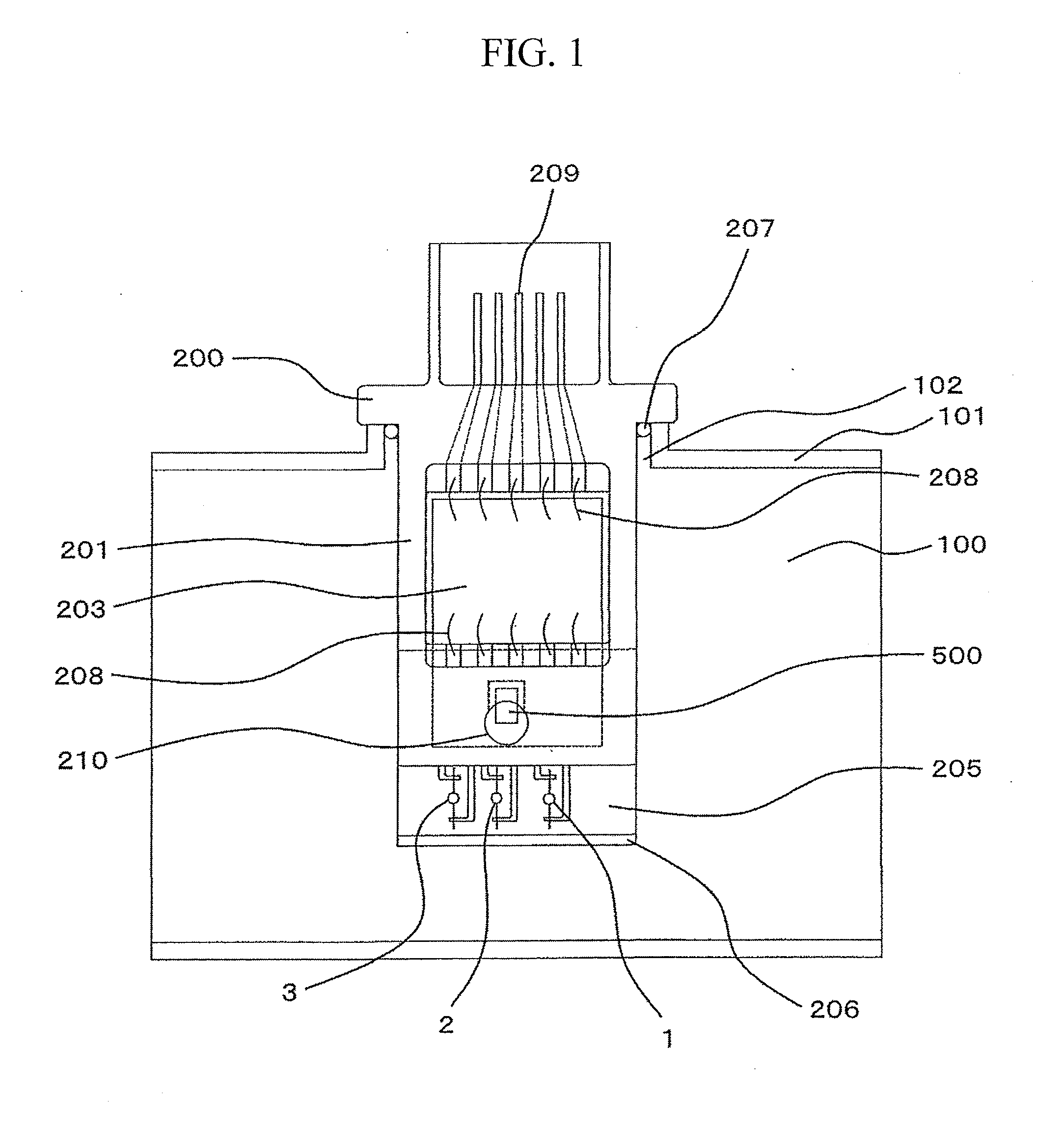
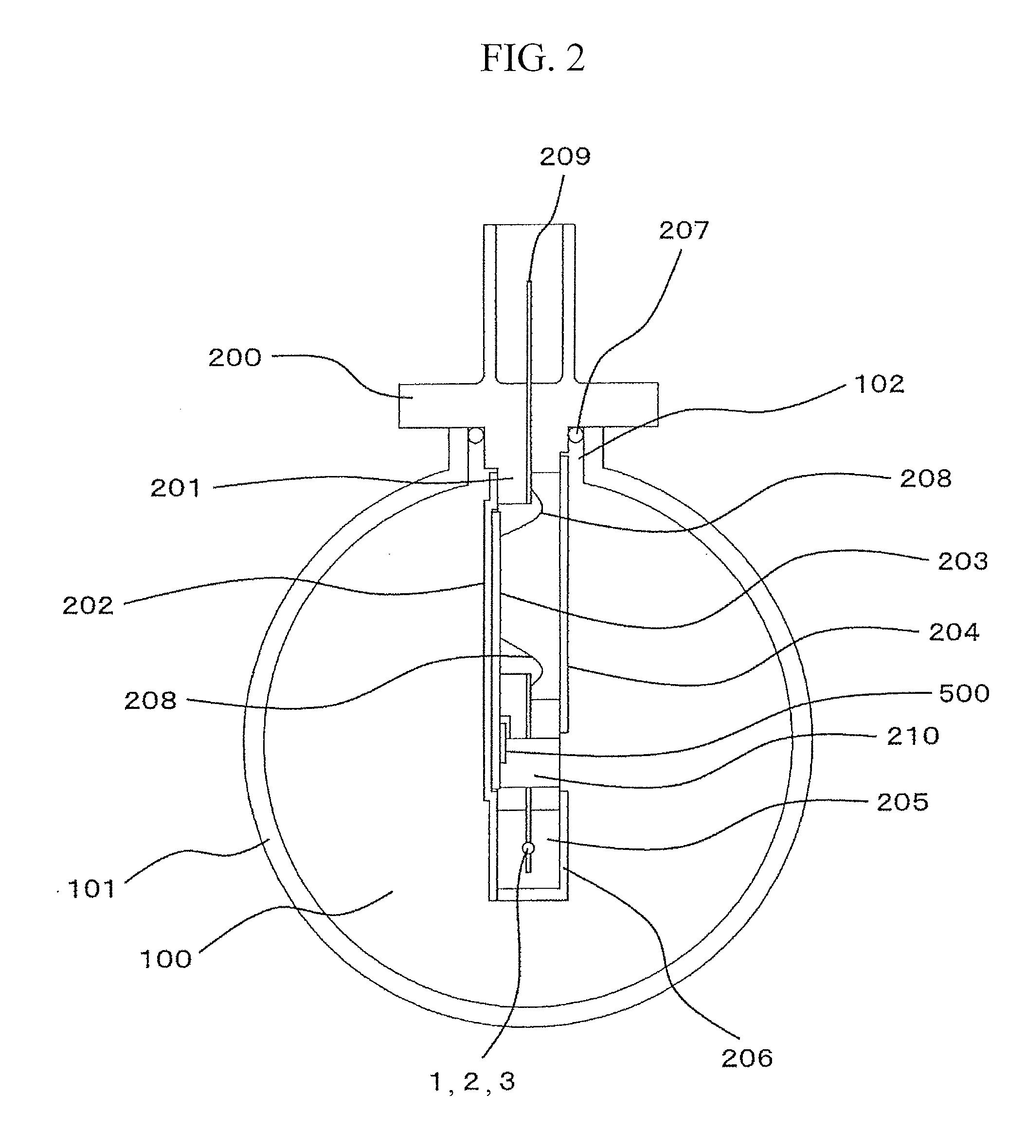
[0072]A specific example of a configuration according to the present invention will be described with reference to FIG. 1. FIG. 2 is a diagram of the configuration in FIG. 1 as seen from the front of the configuration.

[0073]An air flow tube (intake line structural part) 101 forming a main air flow passage (hereinafter also referred to as an intake line or simply an intake tube) 100 includes a sensor installation opening 102 formed in a part of the air flow tube 101 and through which a part of a heating resistor type mass air flow measurement device 200 is inserted. The heating resistor type mass air flow measurement device 200 into which a humidity sensing part 500 is integrated is installed in the air flow tube 101.

[0074]The heating resistor type mass air flow measurement device 200 includes not only a housing structural part 201 but also a base plate 202, a cover 204 configured to protect, an electronic circuit board 203, a heating resistor 1 configured to measure mass air flow, a...


PUM


Abstract

The present invention utilizes self-heating of electronic components to improve a humidity sensing part with low environment resistance, such as a condensation problem and the like, and also to enhance the heat radiation efficiency of electronic components. The humidity sensing part is used in an intake tube of an automobile by integrating, for example, with a heating resister type mass air flow measurement device. A humidity sensing element is mounted on an electronic circuit board in a mass air flow measurement device with the temperature thereof starting to increase immediately after a sensor has been actuated. This urges the temperature of the humidity sensing element to start increasing (being heated) immediately after the sensor has been actuated. To urge the humidity sensing element to be further heated, a base plate is composed of two types of materials, resin and metal. A part of the base plate holding an area of the electronic circuit board generating a large quantity of heat is composed of the metal. A part of the base plate corresponding to the periphery of the humidity sensing part which is to be heated is composed of the resin.

Description

BACKGROUND OF THE INVENTION[0001]1. Field of the Invention[0002]The present invention relates to a sensor integrated structure suitable for physical quantity measurements relating to intake air in an internal combustion engine, and an internal combustion engine control device that uses the sensor integrated structure.[0003]2. Background Art[0004]A heating resistor type mass air flow measurement device is known as a flow measuring technique for internal combustion engines (see JP Patent No. 3523022). The heating resistor type mass air flow measurement device utilizes the correlation of the quantity of heat taken from a heating resistor with inflow discharge. The heating resistor type mass air flow measurement device is capable of directly measuring mass flow required to control combustion in an engine and is thus widely used as a flowmeter for air-fuel ratio control particularly in an automobile.[0005]In connection with a sensor including a flow measurement device, a pressure sensing...

Claims


Application Information

Patent Timeline
IPC IPC(8): G01M15/04G01F1/68
CPCF02D41/187G01F15/02G01F5/00G01F1/6842
Inventor SAITO, TAKAYUKIKOBAYASHI, CHIHIROYOGO, TAKAYUKI
Owner HITACHI ASTEMO LTD
Why Eureka
Try Eureka