High data rate milllimeter wave radio

a millimeter wave radio and high data rate technology, applied in the field of radio systems, can solve the problems of limited available bandwidth in which to transmit as much data, minimal dynamic range variation, and qam techniques that work well on microwave systems

Inactive Publication Date: 2011-03-31
TREX ENTERPRISES CORP
View PDF7 Cites 21 Cited by
  • Summary
  • Abstract
  • Description
  • Claims
  • Application Information

AI Technical Summary

Benefits of technology

[0014]Preferred embodiments are adapted to receive an binary input data stream at an input data rate in excess of 3.5 Gbps and to transmit at a transmit data rate in excess of 3.5 Gbps utilizing encoded three-bit data symbols, on a carrier at a millimeter wave nominal carrier frequency in excess of 70 GHz, with differential phase-shift keying utilizing eight separate phase shifts at a phase-shift rate in excess of 1.16 billion phase shifts per second. To do this, the transmitter includes a frequency stabilized millimeter wave source operating at the millimeter wave carrier frequency; an encoder having an output clocked at said on-off keyed input data rate divided by three and adapted to generate sets of four phase shift modulator control bits, each set representing one of eight three-bit symbols; and a modulator adapted to apply each set of four phase shift modulator control bits from the output of the encoder to the millimeter carrier wave in the form of a single phase shift for each three-bit symbol, each phase shift being one of eight standard, recognizably distinct phase shifts. The receiver is adapted to receive an incoming millimeter wave signal transmitted from a remote millimeter wave transmitter transmitting at frequencies in excess of 70 GHz, said receiver intended to reconstruct communications data sent from the remote transmitter. The receiver includes a millimeter wave amplifier adapted to amplify said incoming millimeter wave signal and a demodulator adapted to decode the incoming millimeter wave signal to produce a binary output data stream at an output data rate in excess of 3.5 Gbps.
[0015]In preferred embodiments operating at data rates in the range of about 3.5 Gbps the occupied transmit bandwidth is preferably between 1.0 GHz and 5 GHz. For data rates of the 10 GigE transceiver the occupied transmit bandwidth is preferably between 3.5 GHz and 5 GHz. Preferably the power spectrum density within more than 70 percent of the output power of the transmitter is constant to within + / −1.5 dB and the transceiver provides provide a dynamic range in power output exceeding 15 dB.

Problems solved by technology

Two key conditions which dictated early microwave radio designs for fixed point-to-point communications were: 1) very limited available bandwidth in which to transmit as much data as possible, and 2) minimal dynamic range variation associated with rain fade and other weather or atmospheric variations.
These QAM techniques work well on microwave systems, but have not been successfully applied to millimeter wave communication systems designed for longer propagation paths (e.g. exceeding a kilometer).
Telephone companies provide communications services to nearly all of the homes and offices in the United States and many other countries, but existing telephone services in many areas provide only low speed (i.e. low data rate) connections.
Communication companies are rapidly improving these last mile services with cable and fiber optic connections, but these improvements are expensive and a large number of people are still without access to high speed communication services.
Microwave radios have been used for many years for last mile and middle mile communication services, but bandwidths for these systems are typically limited such that data rates available are typically much less than 1 Gbps.
Communication companies are beginning to utilize millimeter wave radios to provide these services but the data rates of these radios, although much greater than the microwave systems, are currently limited to about 1 Gbps.
Many cellular systems are becoming overloaded due to the increased bandwidth required by the iPhone 4 and similar consumer products and prior art backhaul facilities are fast becoming inadequate.
Updating these systems is expensive.

Method used


Image

  • High data rate milllimeter wave radio
  • High data rate milllimeter wave radio
  • High data rate milllimeter wave radio

Examples


first preferred embodiment

Applicants' 10-GigE Radio

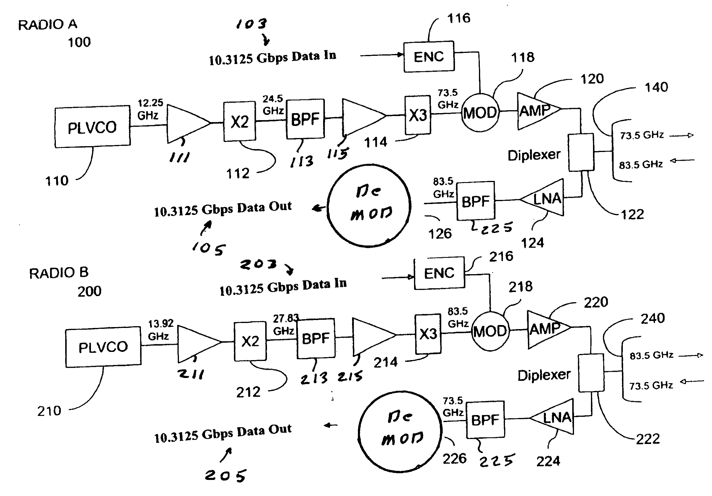
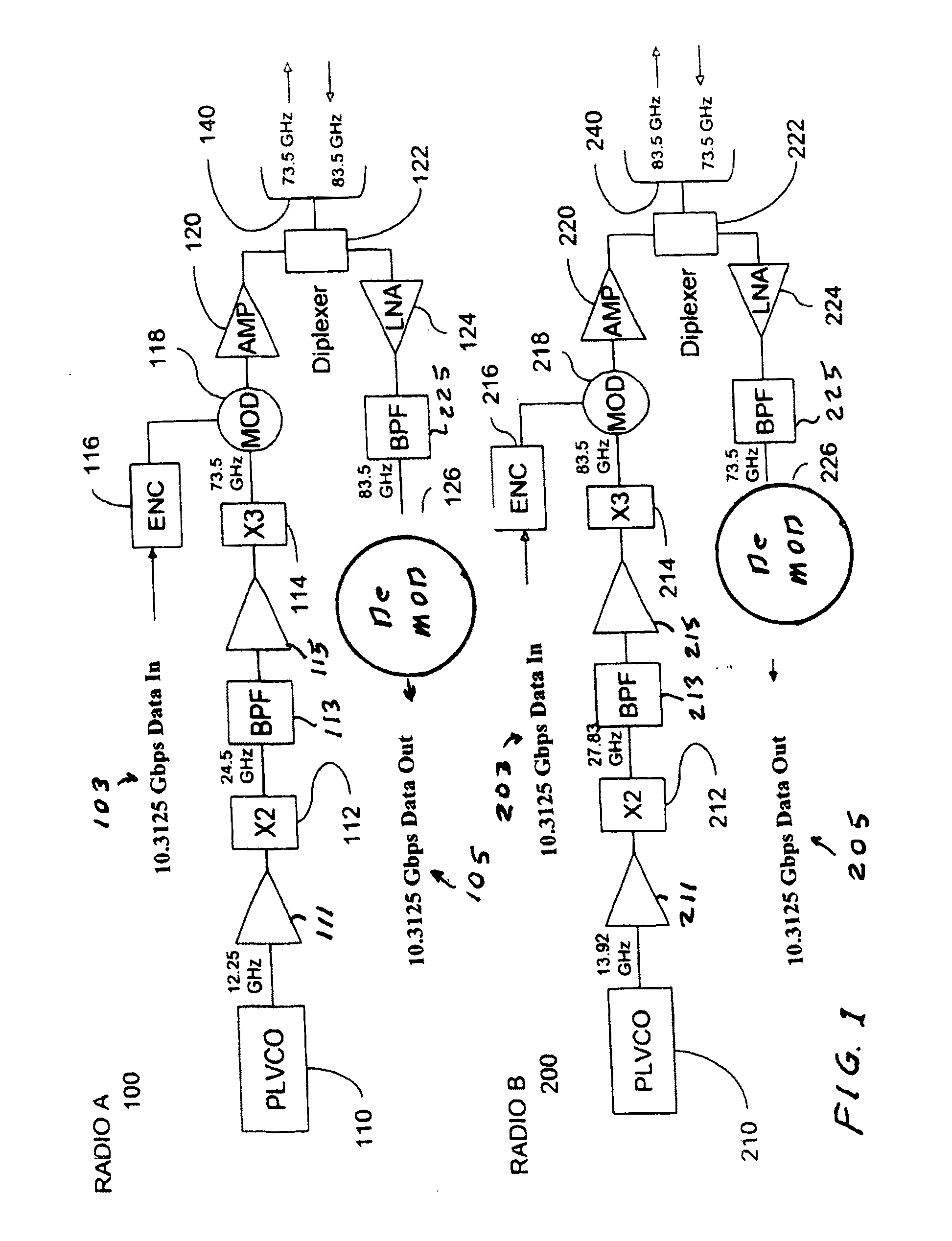
[0025]A first preferred embodiment of the present invention satisfying the needs outlined above is a 10-GigE radio. The radio is based on and is a substantial improvement of the basic circuit design of a 3.072 Gbps radio described in the parent application, of which the present application is a continuation in part. That application is U.S. patent application Ser. No. 12 / 228,114, filed Aug. 7, 2008, Millimeter Wave Radio with Phase Modulation, which is incorporated herein by reference. This parent radio utilized radio circuitry as specifically described in FIG. 3 of the above patent which is reproduced in this application as FIG. 7.

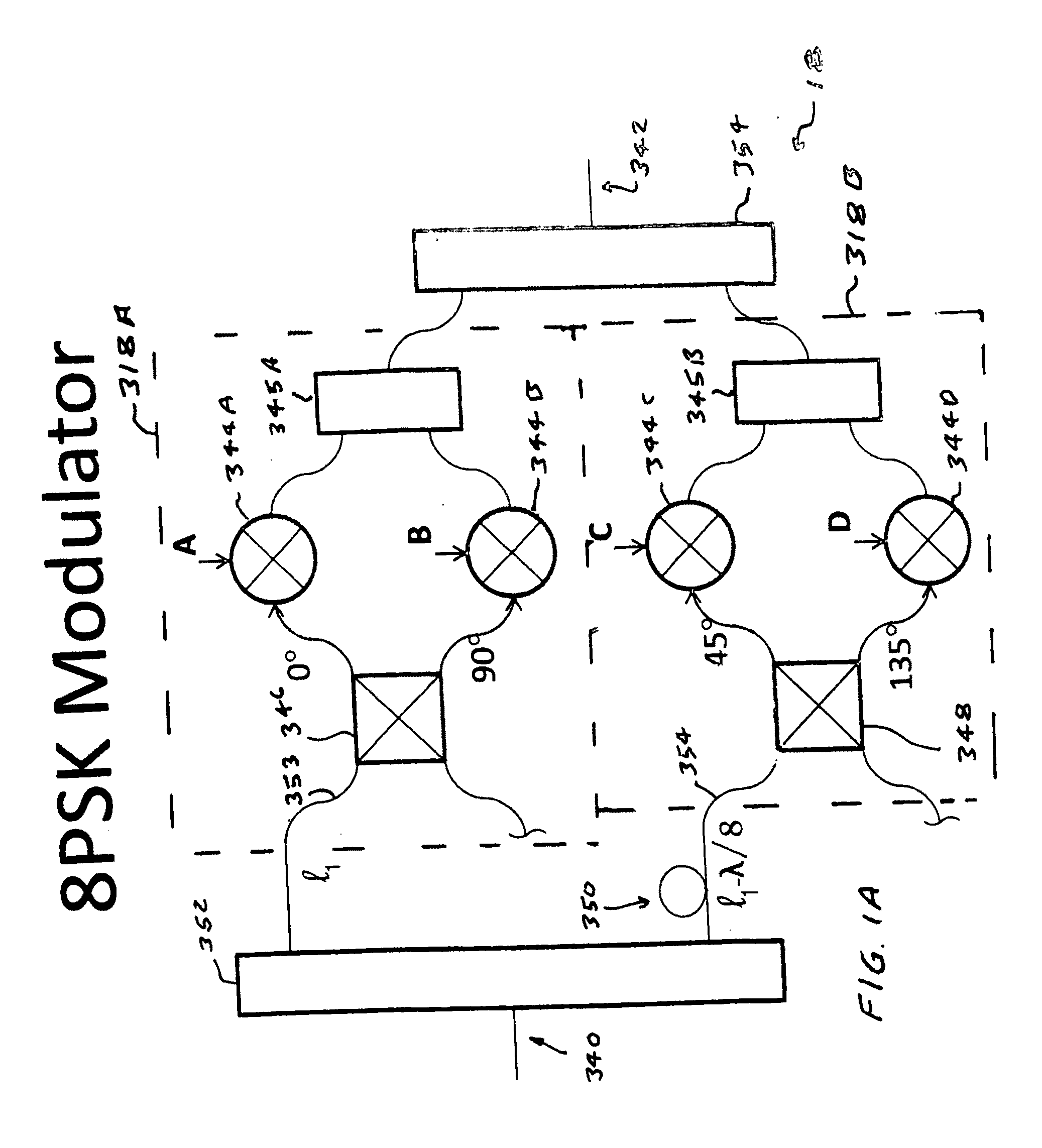
[0026]To support a digital data rate of 10.3125 Gbps (10 Gigabits raw data per second plus IEEE 802.3 Clause 49 64b / 66b encoding which accounts for the excess 0.3125 Gbps), the radio uses 3-bit symbol encoding and has its carrier modulated at a symbol rate of 3.4375 Giga-symbols-per-second so as to fit into the 5 GHz channel modul...


PUM


Abstract

A high data rate millimeter wave radio adapted to receive an binary input data at an input data rate in excess of 3.5 Gbps and to transmit at a transmit data rate in excess of 3.5 Gbps utilizing encoded three-bit data symbols on a millimeter carrier wave at a millimeter wave nominal carrier frequency, defining a carrier wavelength and period, in excess of 70 GHz with differential phase-shift keying utilizing eight separate phase shifts. Preferred embodiments of the invention can support many of the high data rate standards including the following group of protocols or standards: SONET OC-96 (4.976 Gbps); 4xGig-E (5.00 Gbps); 5xGig-E (6.25 Gbps); OBSAI RP3-01 (6.144 Gbps); 6xGig-E (7.50 Gbps); Fibre Channel 8GFC (8.5 Gbps); SONET OC-192 (9.952 Gbps); Fibre Channel 10GFC Serial (10.52 Gbps) and 10 GigaBit Ethernet.

Description

CROSS REFERENCE TO RELATED APPLICATIONS[0001]This application is a continuation in part of U.S. patent application Ser. No. 12 / 228,114, filed Aug. 7, 2008 which is incorporated herein by reference.FIELD OF THE INVENTION[0002]The present invention relates to radio systems and in particular to millimeter wave radio systems.BACKGROUND OF THE INVENTIONMillimeter Wave Radios[0003]In January of 2003, the United States Federal Communications Commission (with encouragement from Applicants' employer and others) affected a new rulemaking in which 10 GHz of bandwidth, comprising (E-Band) frequency channels spanning the extremely high frequency bands from 71 to 76 gigahertz (GHz), 81 to 86 GHz and 92 to 95 GHz. At least 99 percent of the output power should be within these limits which are sometime referred to as the occupied transmit bandwidths. These bands are being used for short range, high bandwidth communications. These bands were opened for point-to-point radio communications without res...

Claims


Application Information

Patent Timeline
Patent Type & Authority Applications(United States)
IPC IPC(8): H04L5/16H04L27/20
CPCH04L27/2332H04L27/2039
Inventor LOVBERG, JOHNCHEDESTER, RICHARD
Owner TREX ENTERPRISES CORP
Why Eureka
Try Eureka