Thermal processing apparatus and cooling method

Active Publication Date: 2011-03-31
TOKYO ELECTRON LTD
View PDF40 Cites 6 Cited by
  • Summary
  • Abstract
  • Description
  • Claims
  • Application Information

AI Technical Summary

Benefits of technology

[0031]According to the thermal processing apparatus and the cooling method of the present invention, the following excellent effects can be provided.
[0032]According to the present invention, in a thermal processing apparatus configured to thermally process a plurality of objects to be processed at the same time, a temperature-lowering gas is mixed with a cooling gas whose temperature has been raised by a heat exchange with respect to a processing vessel, at a position on the upstream side of the heat exchanger. Thus, the use of a special, expensive heat exchanger resistive to a high temperature is eliminated, and it is possible to use a versatile, inexpensive

Problems solved by technology

When the high-temperature air directly flows into th

Method used


Image

  • Thermal processing apparatus and cooling method
  • Thermal processing apparatus and cooling method
  • Thermal processing apparatus and cooling method

Examples


first example

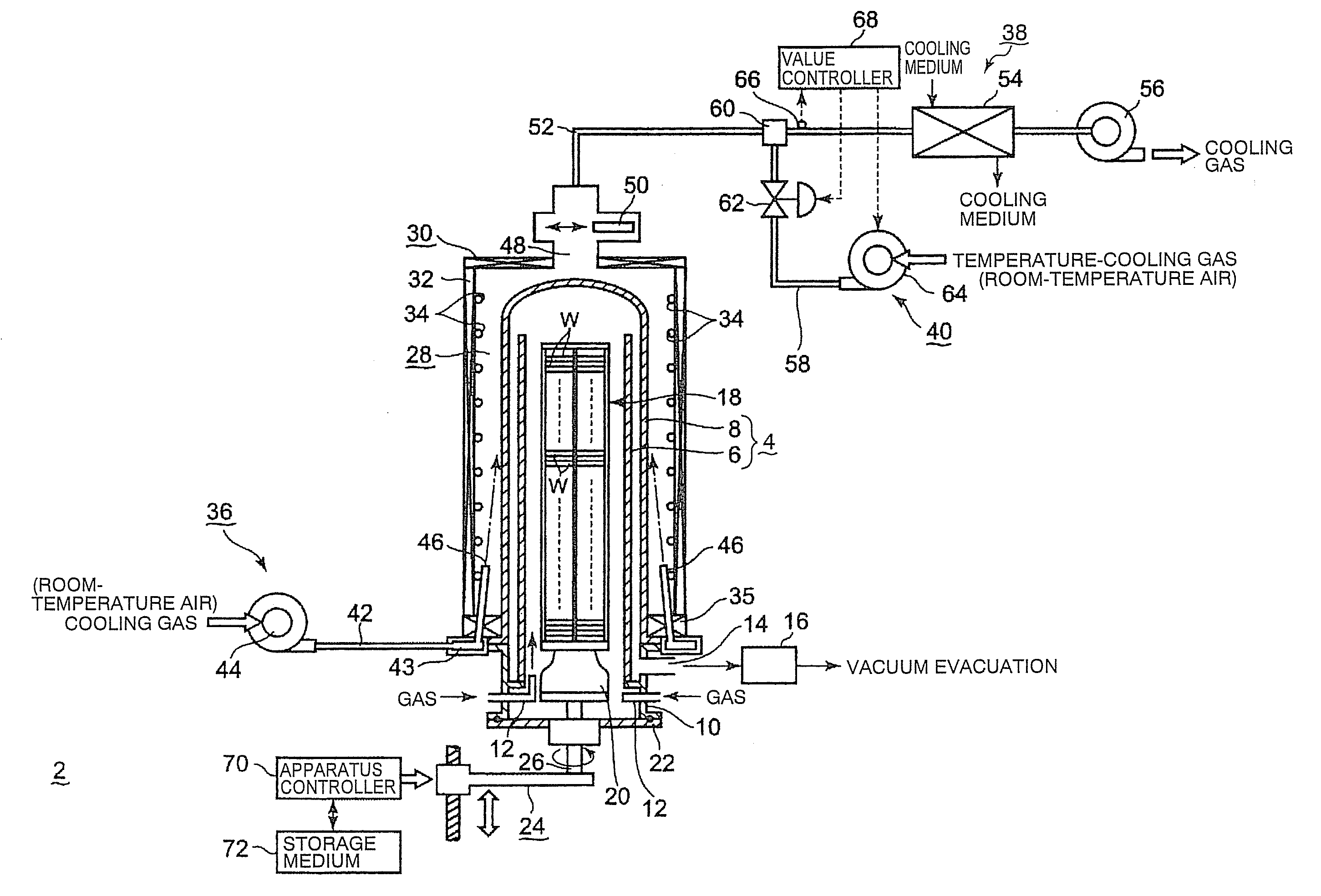
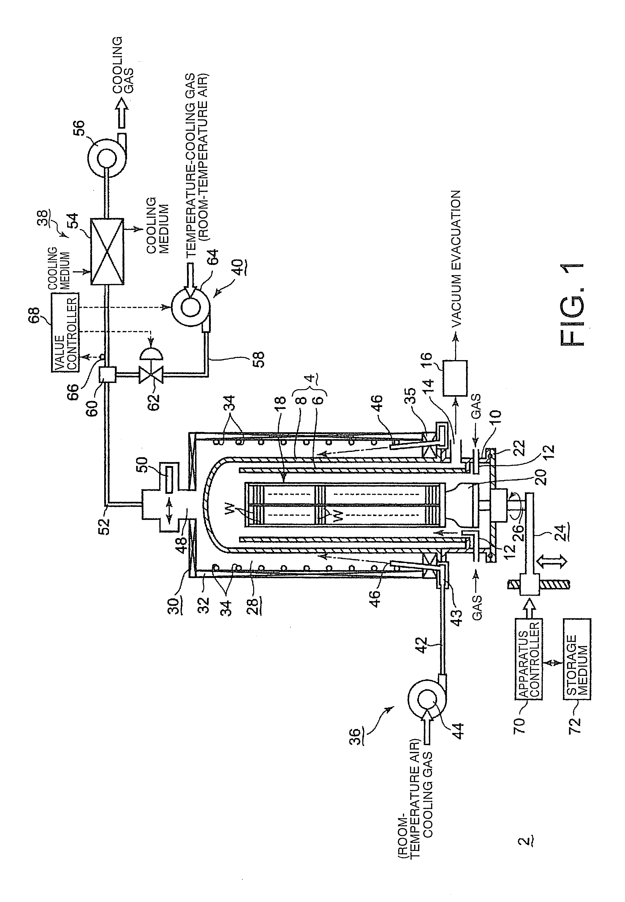
[0042]FIG. 1 is a structural view showing a first example of the thermal processing apparatus according to the present invention. As shown in FIG. 1, the thermal processing apparatus 2 includes a vertically elongated cylindrical processing vessel 4. The processing vessel 4 is of a dual tube structure, which is mainly composed of a cylindrical quartz inner tube 6, and a quartz outer tube 8 that surrounds an outside of the inner tube 6 with a predetermined distance therebetween.

[0043]An upper part of the outer tube 8 is closed to provide a ceiling, and a lower end part thereof is opened to provide an opening. For example, a cylindrical stainless-steel manifold 10 is hermetically connected to the opening. The manifold 10 is provided with a gas introduction unit 12 having a gas nozzle that introduces a required gas into the processing vessel 4, with a flow rate of the gas being controlled. A gas outlet port 14 is formed in a bottom sidewall of the outer tube 8. An exhaust system 16 havi...

second example

[0075]Next, a second example of the thermal processing apparatus according to the present invention will be described. In the above example 1, the temperature-lowering-gas introduction unit 40 is equipped with a gas-temperature measuring unit formed of the thermocouple 66, in order that a temperature of the gas flowing into the heat exchanger is measured. However, not limited thereto, the provision of the gas-temperature measuring unit may be omitted.

[0076]FIG. 4 is a structural view partially showing a second example of the thermal processing apparatus according to the present invention. In FIG. 4, the same constituent parts as those shown in FIG. 1 are shown by the same reference numbers, and detailed description thereof is omitted. As shown in FIG. 4, the gas discharge passage 52 is not equipped with a gas-temperature measuring unit formed of the thermocouple 66, which is shown in FIG. 1. In this case, the valve controller 68 receives a command for starting a cooling operation fr...

third embodiment

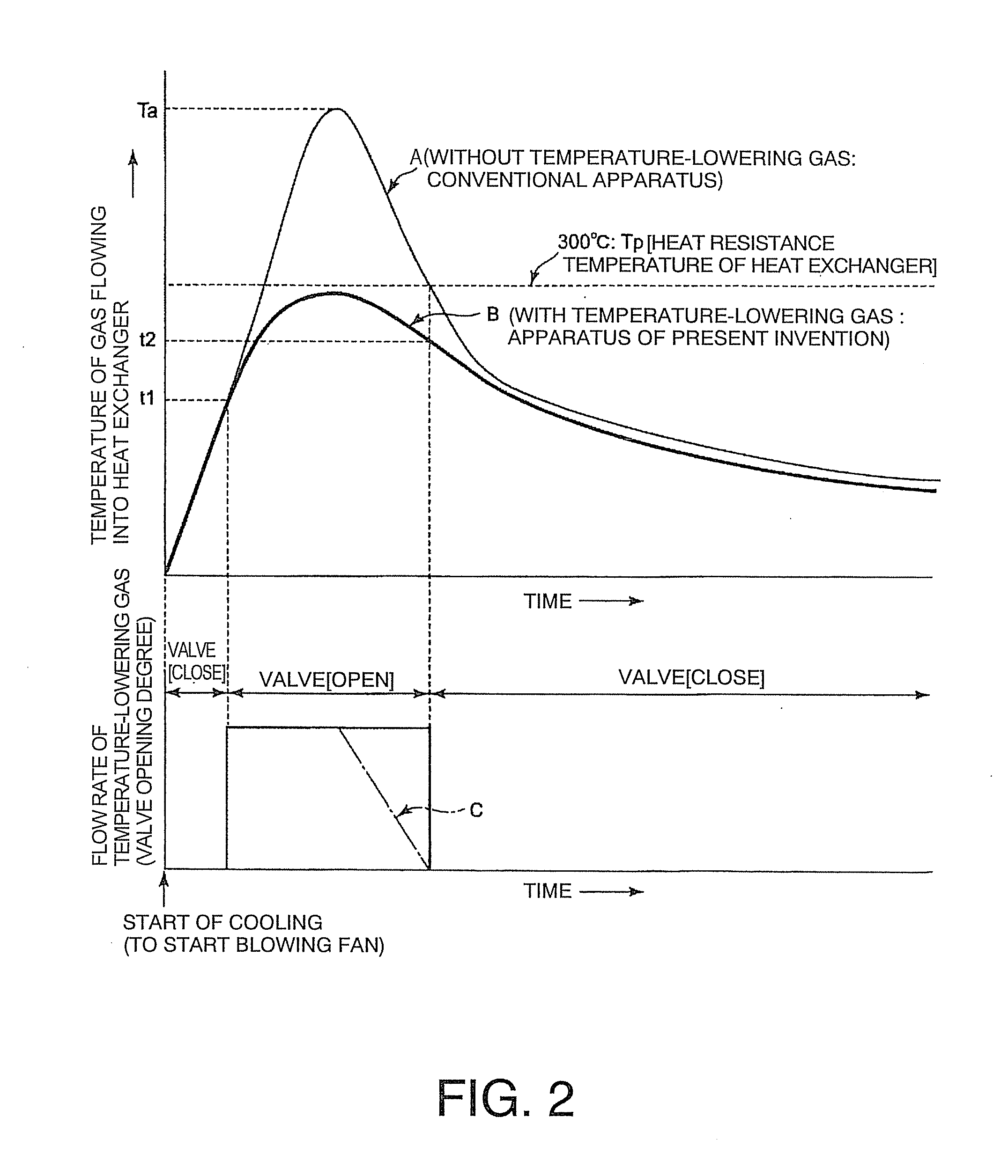
[0078]Next, a third example of the present invention will be described. In the first and second examples, a room-temperature air as the temperature-lowering gas is introduced from the temperature-lowering gas introduction unit 40 that is additionally provided for introducing the temperature-lowering gas. On the other hand, in the third example, a part of the cooling gas (room-temperature gas) sent from the blowing fan is bypassed, and the bypassed cooling gas is introduced into and mixed with the cooling gas whose temperature has been raised during the passage of the cooling space. FIG. 5 is a structural view showing the third example of the thermal processing apparatus according to the present invention. FIG. 6 is a graph showing a relationship between a temperature of a gas flowing into the heat exchanger when the processing vessel is cooled, and an opening and closing operation of a valve on a bypass passage. FIG. 7 is a flowchart showing respective steps of the cooling method in...


PUM


Abstract

A thermal processing apparatus including: a cylindrical processing vessel; a support unit to be loaded into and unloaded from the vessel; and a heating furnace surrounding an outer periphery of the vessel, with a cooling space therebetween. The furnace is connected to a cooling-gas introduction unit, including a gas introduction passage to which a blowing fan is connected, for introducing a cooling gas into the cooling space during a temperature lowering operation after a thermal process. The furnace is connected to a cooling-gas discharge unit, including a heat exchanger, a suction fan, and a gas discharge passage, for discharging the cooling gas of a raised temperature from the cooling space. Connected to the gas discharge passage at a position upstream of the heat exchanger is a temperature-lowering gas introduction unit for introducing a temperature-lowering gas to the cooling gas of a raised temperature so as to lower its temperature.

Description

CROSS REFERENCE TO RELATED APPLICATIONS[0001]This application is based upon the prior Japanese Patent Application No. 2009-221697 filed on Sep. 26, 2009, the entire contents of which are incorporated herein by reference.FIELD OF THE INVENTION[0002]The present invention relates to a batch-type thermal processing apparatus configured to thermally process objects to be processed, such as semiconductor wafers, and a cooling method.BACKGROUND ART[0003]In general, when semiconductor devices are manufactured, semiconductor wafers of silicon substrates are repeatedly subjected to various processes such as a film-deposition process, an etching process, an oxidation and diffusion process, and an annealing process. When a thermal process such as a film-deposition process is performed by a batch-type thermal processing apparatus capable of simultaneously processing a plurality of semiconductor wafers, it is necessary to cool high-temperature semiconductor wafers as fast as possible, while preve...

Claims


Application Information

Patent Timeline
IPC IPC(8): F27D15/02F28D15/00
CPCH01L21/67109C30B25/10C30B35/00
Inventor KUSAKABE, YOSHINORIYAMAGA, KENICHI
Owner TOKYO ELECTRON LTD
Why Eureka
Try Eureka