Exhaust gas treatment device for a CVD device, CVD device, and exhaust gas treatment method

a technology of exhaust gas treatment device and exhaust gas line, which is applied in the direction of auxillary pretreatment, separation process, filtration separation, etc., can solve the problems of inability to assemble components in the exhaust gas line in a very short time, inability to arbitrary thickness, and inability to meet the requirements of exhaust gas line components, etc., to ensure the long durability of components of the exhaust gas line

Inactive Publication Date: 2011-04-14
ROBERT BOSCH GMBH
View PDF6 Cites 9 Cited by
  • Summary
  • Abstract
  • Description
  • Claims
  • Application Information

AI Technical Summary

Benefits of technology

[0006]An object of the present invention is to provide an exhaust gas treatment device for a CVD device for depositing silicon-rich nitride that ensures a long durability of components of the exhaust gas line. In addition, an object of the present invention is to provide a correspondingly optimized CVD device, as well as a method for treating exhaust gas from a CVD process in which silicon-rich nitride is deposited.
[0008]According to an example embodiment of the present invention, an aftertreatment chamber for exhaust gas treatment is provided. The chamber is situated after the actual CVD process, in particular the LPCVD process, it being possible to meter ammonia gas (NH3) into the aftertreatment chamber. The addition of ammonia gas to the exhaust gas of the CVD process forces the deposition of silicon nitride in the aftertreatment chamber, and the reaction of dichlorosilane (DCS) and ammonia gas results in the standard reaction by-products, which can be controlled using conventional exhaust gas treatment methods. In order to enable the deposition of larger quantities of silicon nitride, in particular stoichiometric silicon nitride, it is advantageous to provide a large reaction surface in the aftertreatment chamber. The aftertreatment chamber can thus be constructed in a manner similar to the actual process chamber of the DVD process. It is also possible to provide, as an aftertreatment chamber, an exhaust gas line into which ammonia gas can be introduced. By adding ammonia gas to the exhaust gas from the CVD process, the reaction products that result when silicon-rich nitride is deposited in the actual CVD process chamber can be at least minimized, relieving the burden on the exhaust gas line that is situated after the aftertreatment chamber and that includes at least one cooling trap.
[0009]In order to enable the exhaust gas treatment process to be monitored or controlled in a targeted manner, a specific embodiment is preferred in which the quantity of ammonia gas that is to be added to the exhaust gas can be adjusted in such a way that stoichiometric nitride is deposited. In other words, at least approximately enough ammonia gas is subsequently added that there results in the exhaust gas, in particular in the aftertreatment chamber, a stoichiometric equilibrium between DCS and NH3, so that, at least generally, only exhaust gas exits the aftertreatment chamber, corresponding in its composition at least approximately to the exhaust gas of a stoichiometric CVD deposition process for the deposition of stoichiometric nitride. If warranted, the quantity of ammonia gas to be added to the exhaust gas can also be selected such that there results an excess of ammonia gas in the aftertreatment chamber. An excess of ammonia gas in the exhaust gas exiting the aftertreatment chamber can be controlled relatively easily in terms of the process used.
[0016]In addition, the present invention results in a method for treating exhaust gas from a CVD process, in particular from an LPCVD process, in which silicon-rich nitride is deposited, in particular on a substrate. According to the present invention, it is provided that ammonia gas is added to the exhaust gas from the CVD process, preferably in such a way that stoichiometric nitride is deposited from the exhaust gas. The addition of ammonia gas to the exhaust gas from the CVD process at least reduces an excess of dichlorosilane in the exhaust gas, as well as aggressive reaction products resulting therefrom, and preferably completely balances them, with the advantage that standard reaction products are obtained, in particular NH4Cl, HCl, and H2, as in the case of stoichiometric CVD process control.

Problems solved by technology

The cleaning of exhaust gas for an LPCVD process for depositing stoichiometric silicon nitride is controlled by an exhaust gas pipe heated up to a cooling trap, with an acceptable expense.
A disadvantage of the stoichiometric nitride layer is that this layer stands under a high tensile stress of approximately 1 GPa, and therefore for example cannot be deposited in an arbitrary thickness.
A disadvantage of the processing with an excess of DCS is that the resulting reaction products contained in the exhaust gas are deposited in the exhaust gas line on pipes, valves, and in the cooling trap, which causes failure of components in the exhaust gas line in a very short time.

Method used


Image

  • Exhaust gas treatment device for a CVD device, CVD device, and exhaust gas treatment method
  • Exhaust gas treatment device for a CVD device, CVD device, and exhaust gas treatment method
  • Exhaust gas treatment device for a CVD device, CVD device, and exhaust gas treatment method

Examples


Embodiment Construction

[0023]In the figures, identical components and components having identical functions have been identified with the same reference characters.

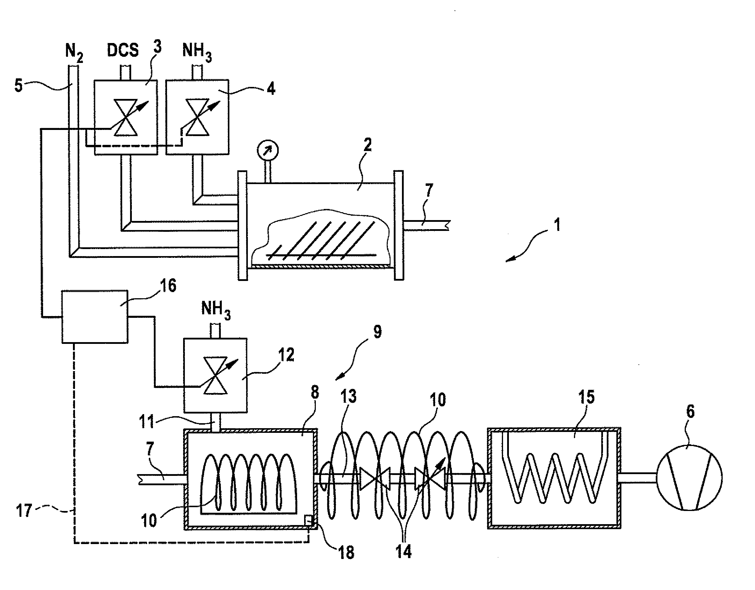
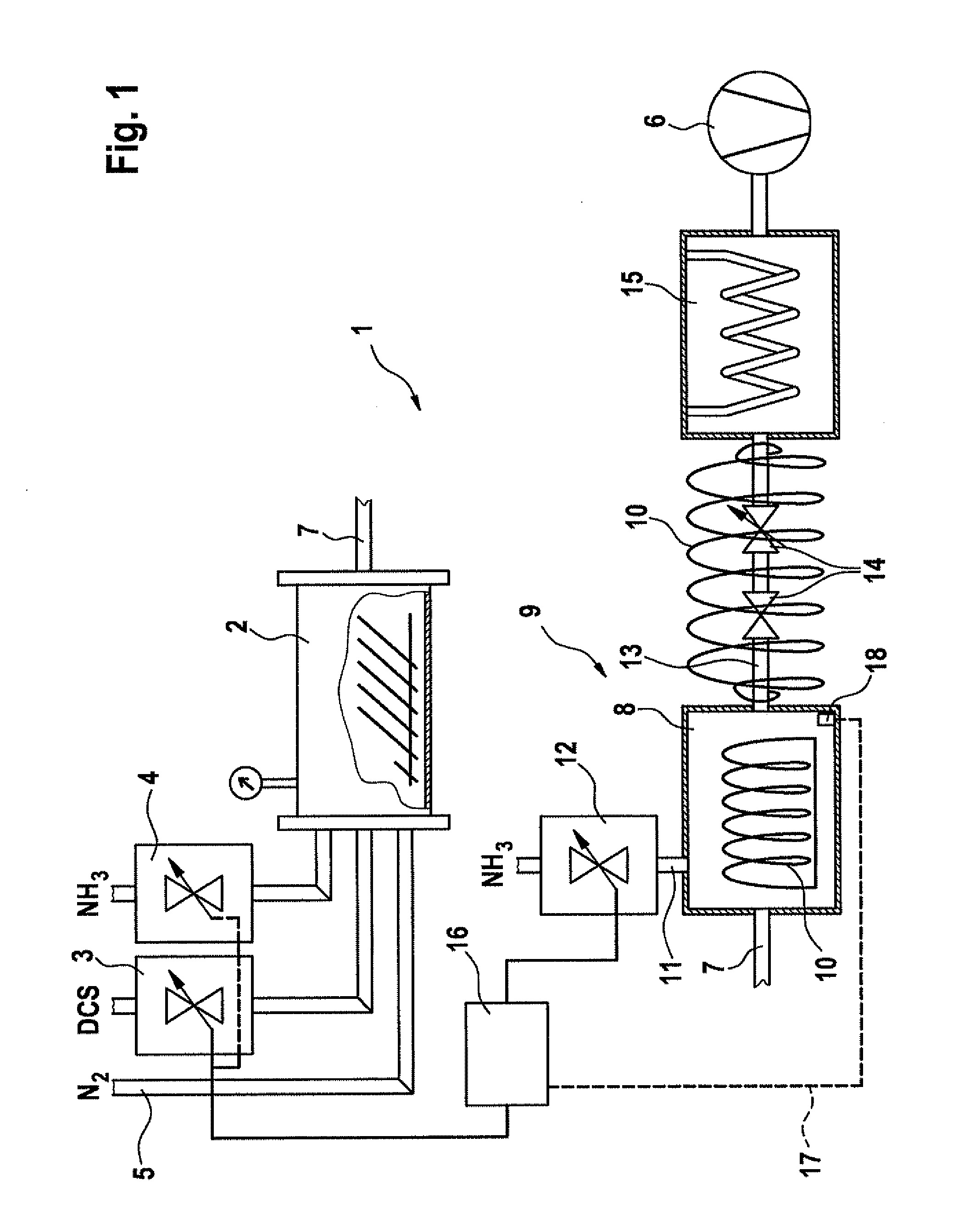
[0024]FIG. 1 shows a CVD device 1 for carrying out an LPCVD process for the deposition of silicon-rich nitride. The CVD

[0025]FIG. 1 shows a CVD device 1 for carrying out an LPCVD process for the deposition of silicon-rich nitride. The CVD device includes a CVD process chamber 2 that is fashioned in a known manner. The CVD process chamber has in its interior one or more substrates, up to typically used batch process sizes, having a large reaction surface, and is capable of being heated (not shown).

[0026]CVD process chamber 2 has allocated to it a dichlorosilane flow quantity controller 3 (mass flow controller) via which the dichlorosilane (DCS) process flow can be adjusted. In addition, CVD process chamber 2 has allocated to it an ammonia gas flow quantity controller 4 (mass flow controller) via which the ammonia gas (NH3) process flow can be co...


PUM

PropertyMeasurementUnit
temperatureaaaaaaaaaa

Abstract

An exhaust gas treatment device for a CVD device for the deposition of silicon-rich nitride in a CVD process, in particular an LPCVD process. An aftertreatment chamber is provided into which ammonia gas can be metered. In addition, a CVD device and an exhaust gas treatment method are described.

Description

FIELD OF THE INVENTION[0001]The present invention relates to an exhaust gas treatment device for a CVD device (Chemical Vapor Deposition device), a CVD device, and a method for treating exhaust gas from a CVD process.BACKGROUND INFORMATION[0002]Conventionally, for the deposition of thin layers, a so-called CVD process (Chemical Vapor Deposition process) is used. In this process, a solid component is deposited from a gas phase on the surface of a substrate in a CVD process chamber on the basis of a chemical reaction. The deposition of layers using a conventional LPCVD (Low Pressure Chemical Vapor Deposition) process, in which the layer is deposited at a low process pressure, is also used. In particular in semiconductor technology and MEMS (Micro-Electro-Mechanical-System) technology, silicon nitride is deposited using an LPCVD process. For this purpose, DCS (dichlorosilane) and NH3 (ammonia gas) are deposited in a stoichiometric equilibrium. The reaction chemistry of this process is ...

Claims


Application Information

Patent Timeline
Patent Type & Authority Applications(United States)
IPC IPC(8): C23C16/56B01D46/46
CPCC23C16/345Y02C20/30C23C16/4412
Inventor RUDHARD, JOACHIMMUELLER, THORSTEN
Owner ROBERT BOSCH GMBH
Why Eureka
Try Eureka