Wave energy converter and power take off system

Active Publication Date: 2011-04-14
OCEAN POWER TECHNOLOGIES
View PDF15 Cites 51 Cited by
  • Summary
  • Abstract
  • Description
  • Claims
  • Application Information

AI Technical Summary

Benefits of technology

[0016]In WECs embodying the invention, the float is coupled to the thrust rod via a relatively coarse system, while t

Problems solved by technology

That is, the PTO may be located externally to the spar; bu

Method used


Image

  • Wave energy converter and power  take off system
  • Wave energy converter and power  take off system
  • Wave energy converter and power  take off system

Examples


Embodiment Construction

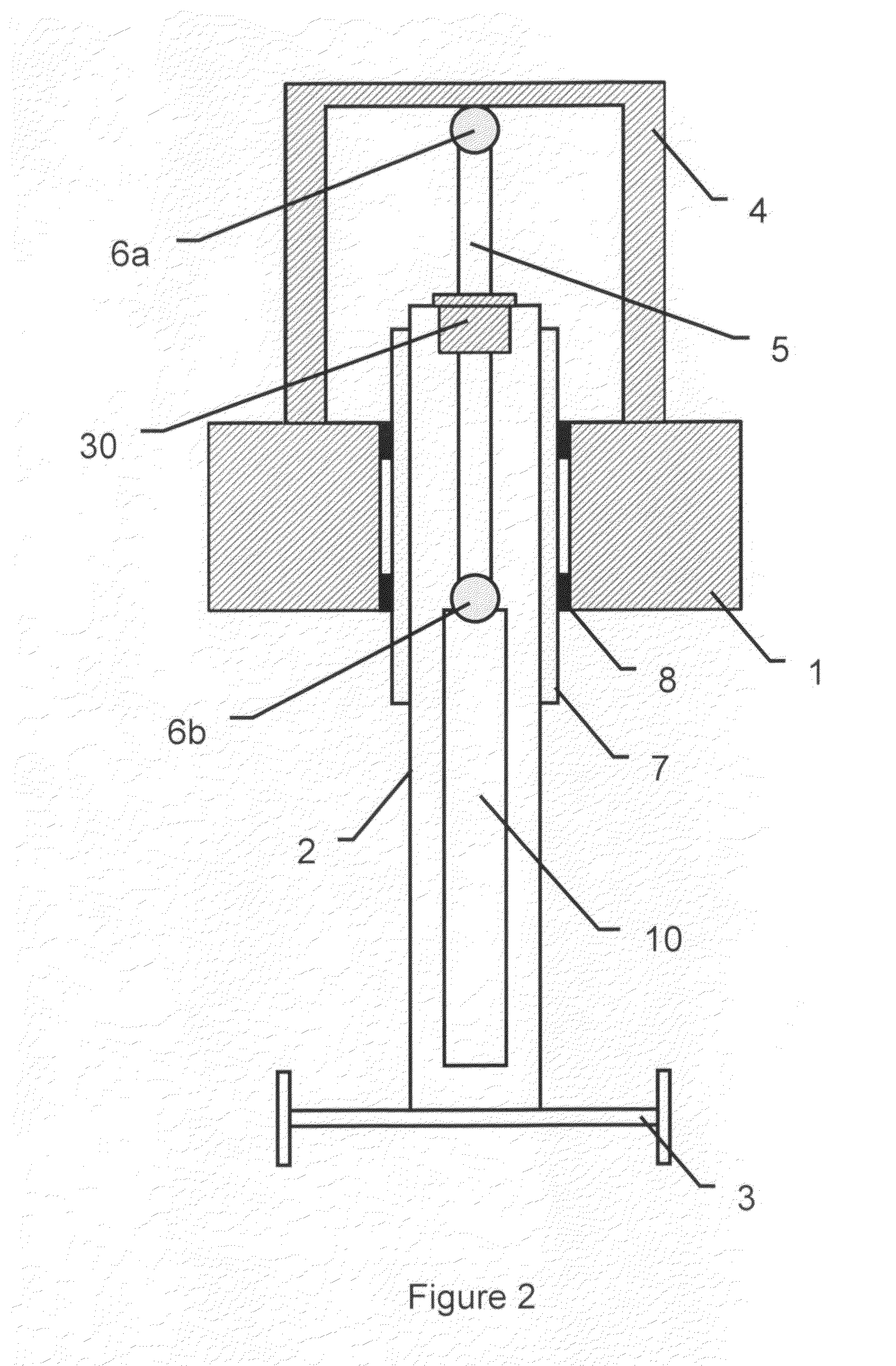
[0026]FIG. 2 shows a WEC which embodies the invention and which is intended to be placed in a body of water subjected to wave motion of varying amplitude and frequency. The WEC includes apparatus suitable for producing reciprocating linear motion. The WEC shown in FIG. 2 includes two major components, a float 1 and a spar2. The float is designed to move generally in phase with the waves and the spar is designed to be stationary, or to move generally out-of-phase with respect to the waves. Thus, in response to the waves in a body of water in which the WEC is positioned, there is relative linear motion between the float and spar.

[0027]In FIG. 2, a heave plate, 3, which may be made of steel, is shown attached to the bottom submerged portion of the spar. The heave plate provides a substantial amount of “added” mass to the spar, allowing it to remain relatively fixed in the water column. This “added” mass is only partly due to the mass of the steel comprising the heave plate 3. It is mos...


PUM


Abstract

A wave energy converter (WEC) includes a float tending to move in phase with the waves, a spar tending to move out of phase with the float and power take off device (PTO) coupled between the float and spar for converting their relative motion into useful energy. The PTO includes a rack and pinion mechanism which drives a high-torque, multi-pole, permanent magnet generator (PMG) to produce electrical signals of relatively high frequency relative to the frequency of the waves and the basic motion of the rack and pinion mechanism. In accordance with one aspect of the invention, the rack and pinion mechanism may be located within the spar which may be hermetically sealed by a sealing mechanism which allows a thrust rod coupled between the float and spar to move up and down with little friction to ensure efficient operation. In addition, a braking arrangement is provided for inhibiting relative motion between the float and spar during extreme severe wave conditions. In this way, the pinion gears and generators need only be sized for the operational wave conditions.

Description

BACKGROUND OF THE INVENTION[0001]This invention relates to Power Take-Off (PTO) apparatus for use with a wave energy converter (WEC) and, in particular, to an improved PTO system employing reciprocating linear motion.[0002]In general, WECs are devices which convert mechanical energy present in ocean waves to electrical energy or any other suitable form of energy. WECs may take many different forms. The present invention is highly suitable for use with WECs which convert the wave energy motion into a reciprocating motion which is substantially linear.[0003]FIG. 1 shows a prior art WEC in which the PTO includes a hydraulic system for driving a generator / motor. The WEC shown in FIG. 1 includes two main components: a toroid-shaped float (1) and a cylindrical-shaped spar (2), with the float (1) being disposed around the spar (2). In this configuration, the float may be designed to be neutrally buoyant whereby its waterline is substantially centered at about halfway of its height. The hyd...

Claims


Application Information

Patent Timeline
IPC IPC(8): F03B13/20
CPCF03B13/186Y02E10/38F05B2220/7068Y02E10/30
Inventor EDER, JAMES E.STEWART, DAVID B.
Owner OCEAN POWER TECHNOLOGIES
Why Eureka
Try Eureka