Highly efficient class-g amplifier and control method thereof

a class-g amplifier, high-efficiency technology, applied in amplifiers, amplifiers with semiconductor devices only, amplifiers, etc., can solve the problems of increased practice implementation costs, distortion and unsuitability, and the output common mode voltage change, so as to achieve the effect of reducing costs and improving efficiency

Inactive Publication Date: 2011-04-14
RICHTEK TECH
View PDF3 Cites 89 Cited by
  • Summary
  • Abstract
  • Description
  • Claims
  • Application Information

AI Technical Summary

Benefits of technology

[0009]Without any charge pumps, the class-G amplifier of the pr

Problems solved by technology

However, this would cause a dramatic change of the output common mode voltage when switching supplies, which causes distortion and is not desirable.
This causes higher costs for practice implementation.
However, the highest efficiency of the charge pump is nowhere

Method used


Image

  • Highly efficient class-g amplifier and control method thereof
  • Highly efficient class-g amplifier and control method thereof
  • Highly efficient class-g amplifier and control method thereof

Examples


Embodiment Construction

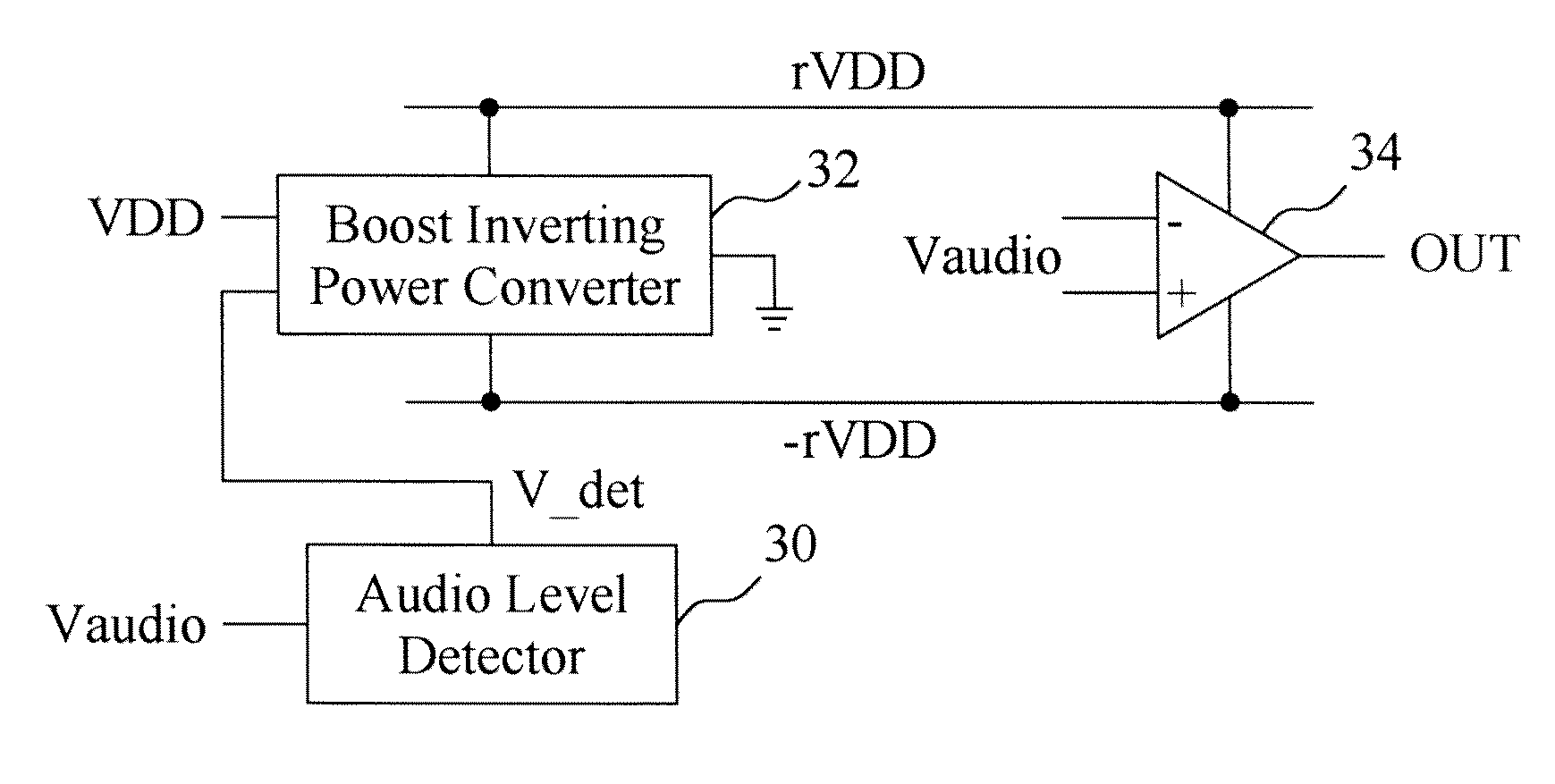
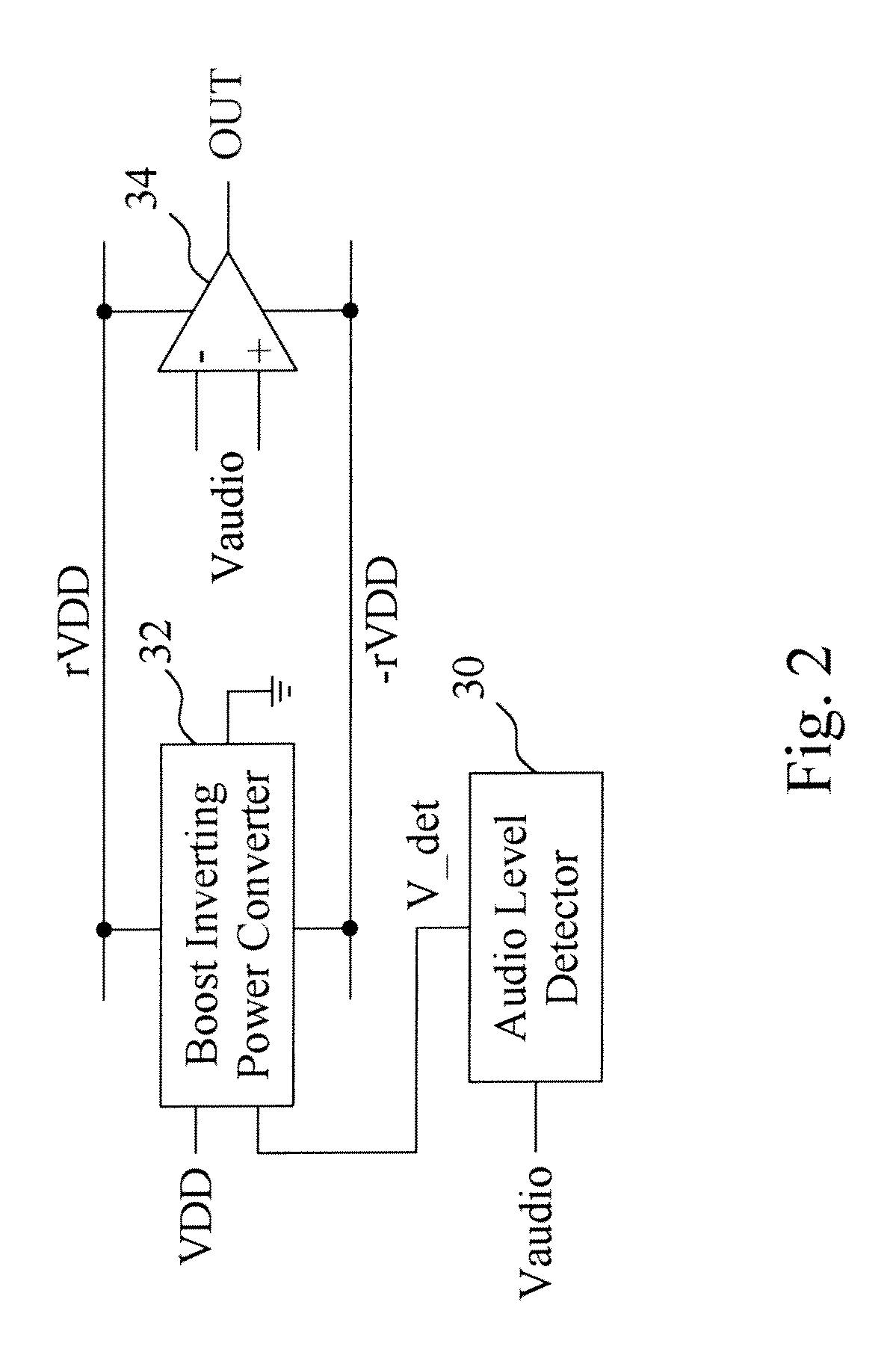
[0017]In an embodiment according to the present invention, as shown in FIG. 2, a class-G amplifier includes an amplifier circuit 34 to amplify the audio input signal Vaudio of the class-G amplifier, a boost inverting power converter 32 coupled to the amplifier circuit 34 to convert a supply voltage VDD to a positive rail voltage rVDD and a negative rail voltage −rVDD for the amplifier circuit 34, and an audio level detector 30 coupled to the boost inverting power converter 32 to detect the audio input signal Vaudio to generate a detection signal V_det for the boost inverting power converter32 to adjust the positive rail voltage rVDD and the negative rail voltage −rVDD. Adjusting power supply is necessary in a class-G amplifier. This embodiment detects the input signal level and adjusts the power supply of the amplifier circuit to achieve the optimization of power dissipation.

[0018]FIG. 3 provides an embodiment for the boost inverting power converter 32, which uses a single-inductor,...


PUM


Abstract

A highly efficient class-G amplifier includes an amplifier circuit coupled between a positive power rail and a negative power rail to amplify an audio input signal of the class-G amplifier, and a boost inverting power converter to convert a supply voltage to a positive rail voltage and a negative rail voltage on the positive and negative power rails. The boost inverting power converter includes a boost inverting power stage coupled to the positive and negative power rails, and a controller to switch the boost inverting power stage between a boost mode and an inverting mode. An audio level detector detects the audio input signal for the controller to adjust the positive and negative rail voltages. The class-G amplifier has higher efficiency and requires lower cost because it does not need a charge pump.

Description

FIELD OF THE INVENTION[0001]The present invention is related generally to a class-G amplifier and, more particularly, to a highly efficient power system for class-G amplifiers.BACKGROUND OF THE INVENTION[0002]A conventional class-G amplifier needs at least four power supplies, typically referred as VCCH, VCCL, VEEH and VEEL. Two power supplies can also be used with the ground as the negative power rail. However, this would cause a dramatic change of the output common mode voltage when switching supplies, which causes distortion and is not desirable. For higher power efficiency, more power supplies need to be added. This causes higher costs for practice implementation.[0003]A recent development uses a buck converter along with a charge pump to provide adjustable VCC and VEE to reduce the hardware implementation costs and improve the efficiency simultaneously. However, the highest efficiency of the charge pump is nowhere near the buck converter and there is a one-clock cycle latency b...

Claims


Application Information

Patent Timeline
IPC IPC(8): H03G3/20
CPCH03F1/0244H03F3/45475H03F2203/45594H03F2203/45528H03F2203/45591H03F2203/45522
Inventor GUO, JWIN-YENWU, TSUNG-NAN
Owner RICHTEK TECH
Why Eureka
Try Eureka