
High utilization universal logic array with variable circuit topology and logistic map circuit to realize a variety of logic gates with constant power signatures

a logic gate and power signature technology, applied in the field of dynamic computing, can solve the problems of high cost of ic design and fabrication, inability to dynamically change the functionality of hardware components such as logic gates or memory latches once the component is fabricated, and inability to connect or reconfigure various hardware components of the computing system during operation, so as to prevent the detection of signal characteristics

Active Publication Date: 2011-04-14
CHAOLOGIX INC
View PDF15 Cites 22 Cited by
  • Summary
  • Abstract
  • Description
  • Claims
  • Application Information

AI Technical Summary

Benefits of technology

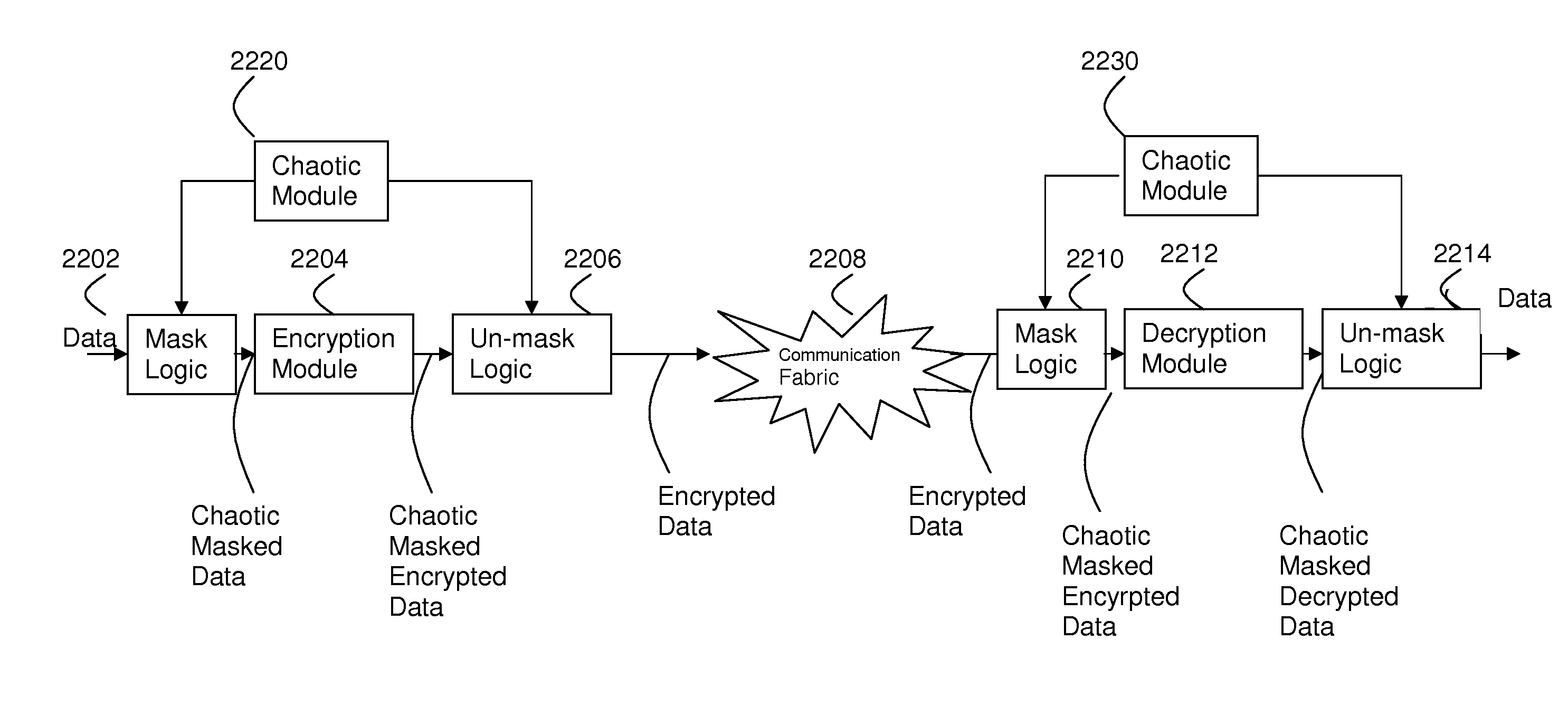
[0013]In another embodiment, a power signature independent topology is described which has properties such that the supply current is independent of input signal state and / or output signal transition and / or control signal state. Such a network has advantages in secure applications where it is desired to prevent detection of signal characteristics by indirect observation of power consumption. The technique may be further enhanced by providing a masking of input data based on mathematics of chaos theory.

Problems solved by technology

Within static computing systems, the various hardware components of the computing system cannot be reconnected or reconfigured during operation.
For example, the functionality of hardware components such as logic gates or memory latch cannot be dynamically changed once the component is fabricated.
Due to the high cost of IC design and fabrication, companies have looked for ways to avoid the majority of IC fabrication costs by utilizing hardware that is electrically or metal / via programmed.
An issue with FPGA technology is that to support any application, the overhead required for flexible logic and interconnect is extremely high.
This unused circuitry is inefficient, for both simple and complex functions.
Moreover, there may be large amounts of the array simply not utilized because the total logic requirement is well below the array capability.
These issues may not be problematic if designs have a low run rate in manufacturing, but if millions of pieces are required then customers lose margin by paying for silicon not utilized.
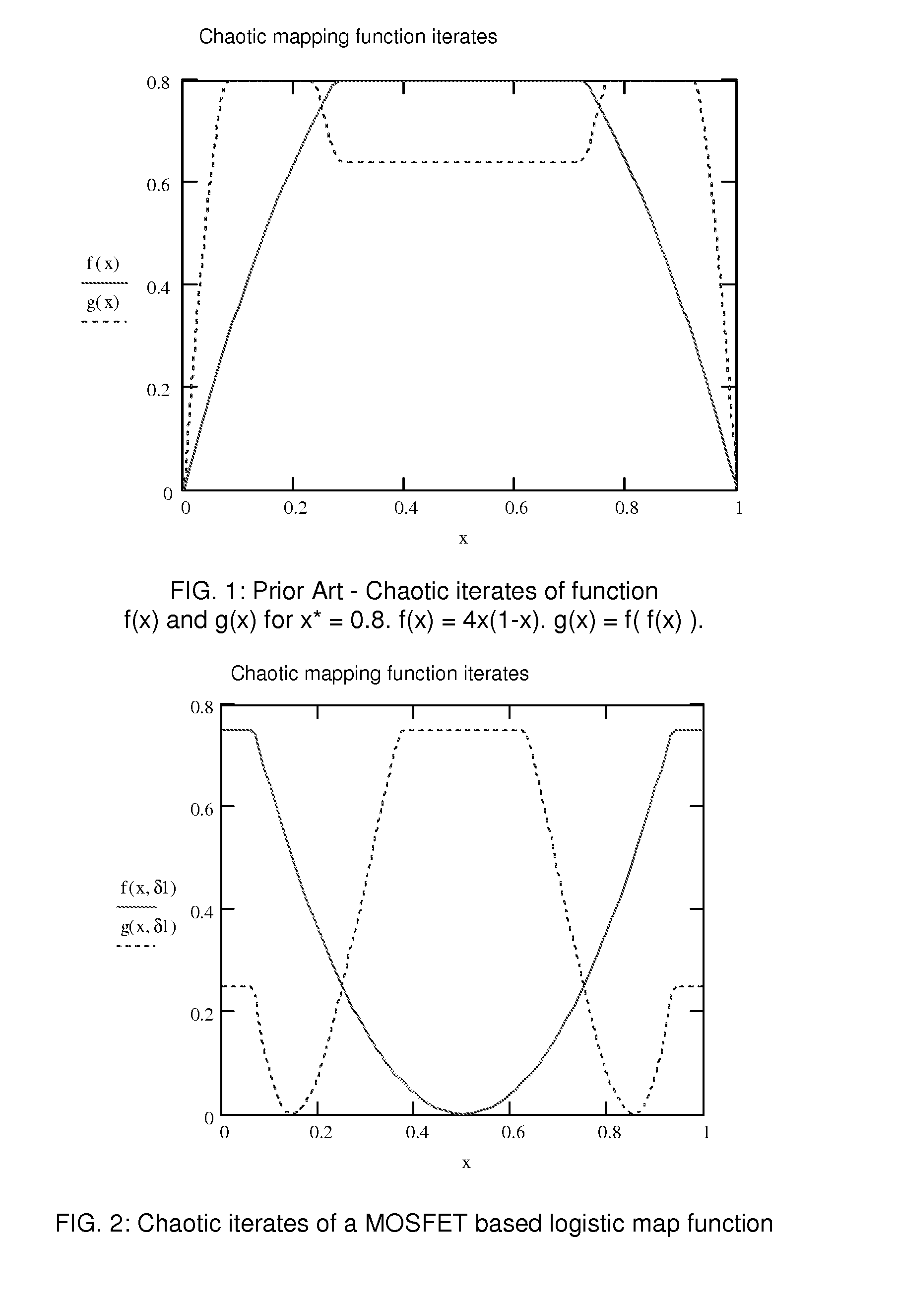
Chua's circuit, although easy to implement with off the shelf discrete components, is not feasible to manufacture using integrated circuit technology because the necessary inductors and capacitors consume too much circuit area and the large number of operational amplifiers necessitate numerous transistors.
Moreover, integrated circuits based on Chua's circuit, are often very difficult to control because the component values are very sensitive.

Method used


Image

  • High utilization universal logic array with variable circuit topology and logistic map circuit to realize a variety of logic gates with constant power signatures
  • High utilization universal logic array with variable circuit topology and logistic map circuit to realize a variety of logic gates with constant power signatures
  • High utilization universal logic array with variable circuit topology and logistic map circuit to realize a variety of logic gates with constant power signatures

Examples


Embodiment Construction

[0037]What is provided is a novel circuit able to generate any logic combination possible as a function of the input logic signals. The circuit is described as a 2 input circuit but may be expanded to 3 or more inputs as required. Further disclosed is a universal logic array with variable circuit topology. A metallization layer and / or a via connection between cells in the array elements produce a circuit topology that implements a Boolean function and / or chaotic function and / or a logic function.

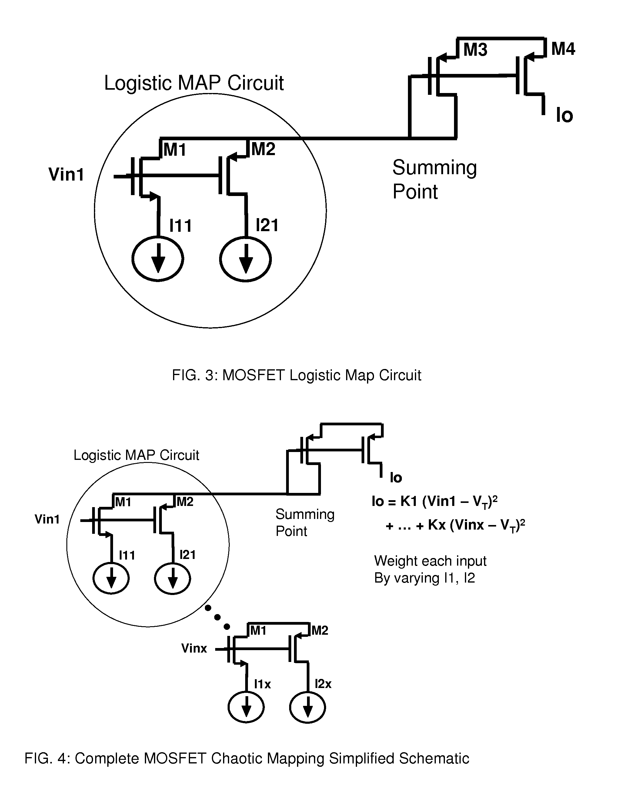
[0038]The logistic mapping network of the present invention provides many advantages over prior art solutions. The logic map can realize any logic function and can be extended to 3 or more inputs through use of appropriate input multiplexing. The universal logic gate has greater functionality with fewer transistors than prior art along with a standard CMOS logic interface. Unlike prior art solutions no analog threshold inputs are necessary. The resulting current of the logistic map network ac...


PUM


Abstract

Disclosed is a novel circuit able to generate any logic combination possible as a function of the input logic signals. The circuit is described as a 2 input logistic map circuit but may be expanded to 3 or more inputs as required. Further disclosed is a universal logic array with variable circuit topology. A metallization layer and / or a via interconnection between cells in the array elements produce a circuit topology that implements a Boolean function and / or chaotic function and / or a logic function. The novel circuit provides a circuit topology for secure applications with no obvious physical correspondence between control signal values and input to output mapping. Further disclosed is a network which has a power signature independent of input signal state and output transition. This provides a very useful circuit to protect data from decryption from power signature analysis in secure applications.

Description

CROSS-REFERENCE TO RELATED APPLICATIONS[0001]This application is based upon and claims priority from U.S. Provisional Patent Application No. 61 / 251,519, Attorney Docket No. 513-V0004, filed on Oct. 14, 2009 and U.S. Provisional Patent Application No. 61 / 358,664, Attorney Docket No. 513-V0005, filed on Jun. 25, 2010, the entire disclosure of each individual aforementioned application is herein incorporated by reference in their entirety.TECHNICAL FIELD[0002]The present invention generally relates to the field of dynamic computing and, more particularly, to configurable computing architectures for logic gates using non-linear elements and a universal logic array with variable circuit topology.BACKGROUND[0003]Conventional computing systems rely on static combinations of logic gates to implement one or more predefined Boolean algebraic functions and / or memory. Within static computing systems, the various hardware components of the computing system cannot be reconnected or reconfigured d...

Claims


Application Information

Patent Timeline
Patent Type & Authority Applications(United States)
IPC IPC(8): H04K1/02H03K19/00H03K19/094
CPCH03K19/17704H04L9/001H04L9/003H04L2209/046H04L2209/12H03K19/17728H03K19/20H03K19/17768H03K19/0013H03K19/0944H01L2924/0002H01L2924/00G06F21/755
Inventor MYERS, BRENT A.FOX, JAMES G.
Owner CHAOLOGIX INC
Learn More