Fuel gas ignition system for gas burners including devices and methods related thereto

a technology of fuel gas ignition and burner, which is applied in the direction of gaseous heating fuel, failure to ignite, domestic stoves or ranges, etc., can solve the problems of continuous generation of sparks, electrical and physical noise produced by sparks, and known ignition modules for gas-fired burners,

Inactive Publication Date: 2011-04-14
COORSTEK INC
View PDF70 Cites 15 Cited by
  • Summary
  • Abstract
  • Description
  • Claims
  • Application Information

AI Technical Summary

Benefits of technology

[0013]The present invention features a fuel gas ignition system and methods for controlling fuel...

Problems solved by technology

Problems with spark-type igniters, however, include among other things the electronic and physical noise produced by the spark.
Known ignition modules for gas-fired burners, however, are susceptible to malfunctions in use.
In addition, the modules are often sensitive to voltage on the neutral conductor which desensitizes the flame detection circuit and can lead to continuously generated sparks despite the presence of a flame on a burner.
If the electrical junction box is not properly wired, the i...

Method used


Image

  • Fuel gas ignition system for gas burners including devices and methods related thereto
  • Fuel gas ignition system for gas burners including devices and methods related thereto
  • Fuel gas ignition system for gas burners including devices and methods related thereto

Examples


Embodiment Construction

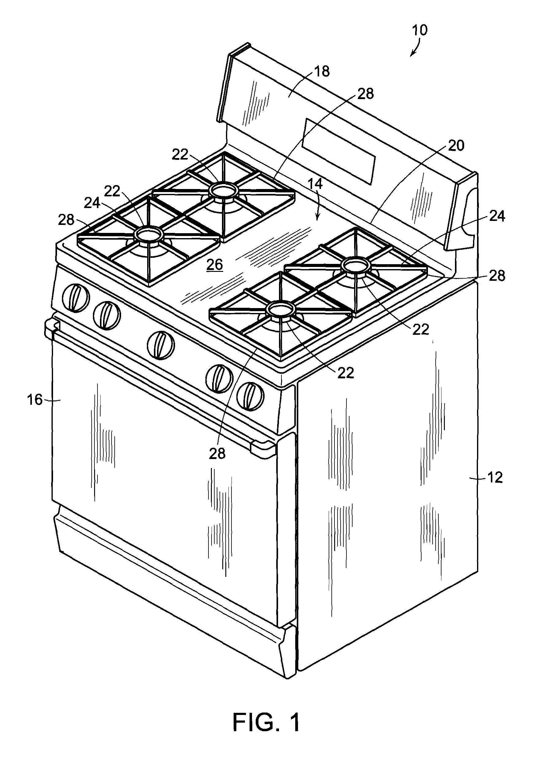
[0038]Referring now to the various figures of the drawing wherein like reference characters refer to like parts, there is shown in FIG. 1 an exemplary conventional free standing gas range 10 that includes an outer body or cabinet 12 that incorporates a generally rectangular cooktop 14. An oven, not shown, is positioned below cooktop 14 and has a front-opening access door 16. A range backsplash 18 extends upward of a rear edge 20 of cooktop 14 and contains various control selectors (not shown) for selecting operative features of the heating elements for cooktop 14 and the oven.

[0039]In the exemplary free standing gas range 10, the cooktop 14 includes four gas fueled burners 22 which are positioned in spaced apart pairs positioned adjacent each side of the cooktop. Typically, each pair of burners 22 is surrounded by a recessed area 24 of the cooktop 14. The recessed areas 24 are positioned below an upper surface 24 of the cooktop 14 and typically serve to catch any spills from cooking...


PUM


Abstract

Featured is a gas burner ignition system using miniaturized hot surface igniters of various types configurations and material systems: The ignition system includes an electronic microprocessor which controls both the igniter operation and all functions of the ignition system.

Description

CROSS REFERENCE TO RELATED APPLICATIONS[0001]This application claims the benefit of U.S. Provisional Application Ser. No. 60 / 225,891 filed Jul. 15, 2009, the teachings of which are incorporated herein by reference.FIELD OF INVENTION[0002]The present invention relates to control systems for fuel burner igniters and more particularly to control systems for electrical resistance-type igniters for fuel burners and methods for controlling the voltage thereto.BACKGROUND OF THE INVENTION[0003]There are a number of appliances such as cooking ranges and clothes dryers and heating apparatuses such as boilers and furnaces in which a combustible material, such as a combustible hydrocarbon (e.g., propane, natural gas, oil) is mixed with air (i.e., oxygen) and continuously combusted within the appliance or heating apparatus so as to provide a continuous source of heat energy. This continuous source of heat energy is used for example to cook food, heat water to supply a source of running hot water...

Claims


Application Information

Patent Timeline
IPC IPC(8): F23N5/00
CPCF23N5/242F23N2027/02F23N2027/42F24C3/103F23N2031/08F23N2041/08F23Q7/10F23N2029/12F23N2227/02F23N2227/42F23N2229/12F23N2231/08F23N2241/08
Inventor CHODACKI, THOMAS A.TANGUAY, MICHAEL W.
Owner COORSTEK INC
Why Eureka
Try Eureka