Improved techniques for magnetic particle imaging

a magnetic particle and imaging technology, applied in the field of volume imaging, can solve the problems of untuned receiver coil, unoptimized preamplifier matching, unsatisfactory reconstructed image from n harmonic images, etc., and achieve the effect of efficient performan

Active Publication Date: 2011-04-21
RGT UNIV OF CALIFORNIA
View PDF14 Cites 43 Cited by
  • Summary
  • Abstract
  • Description
  • Claims
  • Application Information

AI Technical Summary

Benefits of technology

[0009]In some embodiments implementing intermodulation MPI, the excitation field electromagnets comprise low-frequency excitation electromagnets driven by a low-frequency excitation signal and radio-frequency excitation electromagnets driven by a radio-frequency excitation signal. The excitation field electromagnets may include multiple pairs of electromagnets, wherein the multiple pairs are oriented in mutually orthogonal directions. Preferably, the excitation circuitry includes a filter that suppresses harmonics of the fundamental radio frequency excitation signal. The excitation circuitry preferably also includes feedback circuitry that prevents phase and magnitude drift in excitation field strength.
[0019]In some embodiments, a second trajectory is computed from the first image of the distribution of the magnetic particles, and the scanning magnetic field is modified to cause the field-free region to follow the second trajectory within the imaging region. Preferably, the method is efficiently performed so that the first image and second image are produced in real time. In some embodiments, the scanner follows a first low resolution trajectory. If magnetic particles are found at a specific point in the low resolution trajectory, the scanner immediately scans a second trajectory in a neighborhood of that point with higher spatial resolution. The scanner then moves to the next point in the first trajectory.

Problems solved by technology

Because these harmonics span a large bandwidth, detecting them poses challenges for the receiver design.
Gleich et al. use an un-tuned receiver coil, which can not be optimally matched to the preamplifier, to detect the signals over this large bandwidth.
However, there are several challenges with their technique.
Also, their image reconstructed from the N harmonic images is not optimal.
Moreover, conventional deconvolution algorithms can lead to pernicious noise amplification when applied outside of their original context of a single image blurred by a single point spread function.
However, the magnetic particle contrast agent is likely to be substantially sparse, meaning many of these voxels are substantially void of contrast and, hence, signal.
Consequently, the sampling method is inefficient and slow.

Method used


Image

  • Improved techniques for magnetic particle imaging
  • Improved techniques for magnetic particle imaging
  • Improved techniques for magnetic particle imaging

Examples


Embodiment Construction

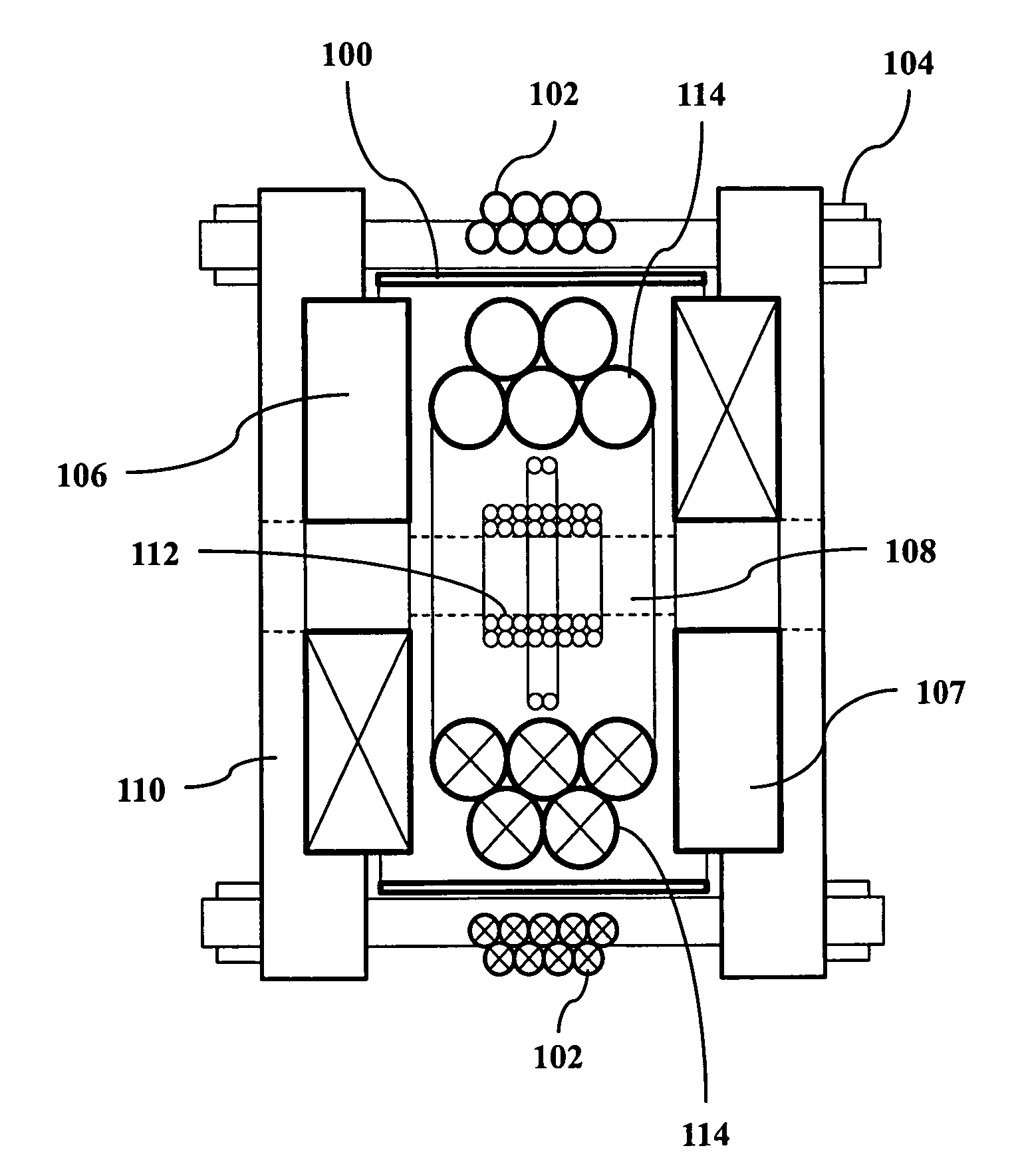
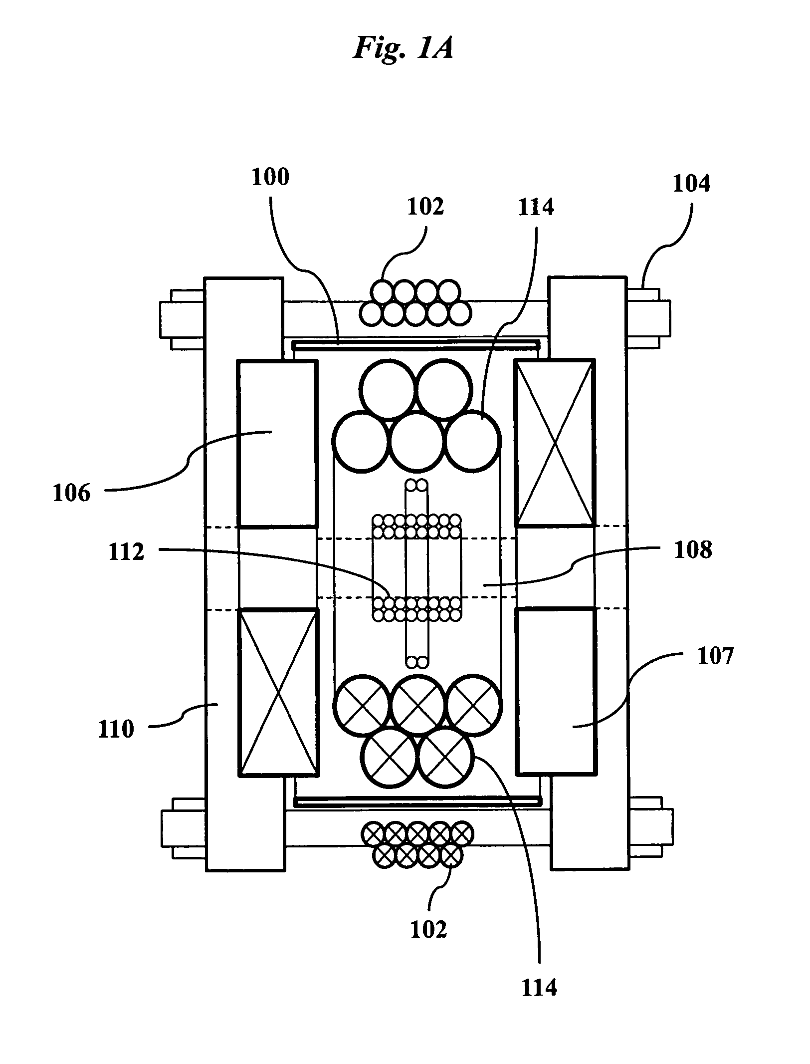
[0039]An MPI apparatus according to an embodiment of the invention is shown in FIG. 1A. NdFeB ring magnets 106, 107 create a static inhomogeneous magnetic gradient field having a field-free region located near the center of imaging bore 108. Ring magnets 106, 107 have a mean diameter of 7.62 cm and a center-to-center separation of 6.85 cm. The magnetic field is approximately linear axially down the bore, with a gradient of dB / dz=4.5 T / m. Coronal gradients are dB / dx=dB / dy=2.6 T / m. Water-cooled excitation solenoid 114 generates a dynamic magnetic field that is superimposed on the static field and can excite magnetic particles in the imaging bore 108. In addition, intermodulation solenoid 102 generates a dynamic magnetic field that is also superimposed on the static field. Magnetic shield 100 passively isolates the AC excitation solenoids 102 and 114 from interaction with other components to reduce unwanted heating and signal interference. Signals from magnetic particles located in the...


PUM


Abstract

A magnetic particle imaging apparatus includes magnets [106,107] that produce a gradient magnetic field having a field free region (FFR), excitation field electromagnets [102,114] that produce a radiofrequency magnetic field within the field free region, high-Q receiving coils [112] that detect a response of magnetic particles in the field free region to the excitation field. Field translation electromagnets create a homogeneous magnetic field displacing the field-free region through the field of view (FOV) allowing the imaging region to be scanned to optimize scan time, scanning power, amplifier heating, SAR, dB / dt, and / or slew rate. Efficient multi-resolution scanning techniques are also provided. Intermodulated low and radio-frequency excitation signals are processed to produce an image of a distribution of the magnetic nanoparticles within the imaging region. A single composite image is computed using deconvolution of multiple signals at different harmonics.

Description

FIELD OF THE INVENTION[0001]The present invention relates generally to methods and devices for volume imaging. More specifically, it relates to improved techniques for magnetic particle imaging.BACKGROUND OF THE INVENTION[0002]Magnetic particle imaging (MPI) is a young and developing volumetric imaging technique first proposed in 2005 that directly detects the magnetization from magnetic particles without depth limitations. MPI has important applications to medical imaging, e.g., heart and blood vessel imaging, cell tracking, and cancer detection. The basic principle of MPI involves exciting magnetic particles in a selected region (e.g., magnetic particle contrast agents injected into the blood stream or labeled into or on cells) and detecting their non-linear response. An inhomogeneous magnetic field having a field-free region and a strong field outside this region selects the particles that will be detected. Such a field may be established, for example, using two permanent magnets...

Claims


Application Information

Patent Timeline
Patent Type & Authority Applications(United States)
IPC IPC(8): G01R33/12
CPCG01R33/10A61B5/0515G01R33/1269G01R33/1276A61B5/7257A61B5/05G01R33/0213G01N27/72G01R33/00
Inventor GOODWILL, PATRICK W.CONOLLY, STEVEN M.
Owner RGT UNIV OF CALIFORNIA
Why Eureka
Try Eureka