Oil immersed electrical apparatus
an electrical apparatus and oil immersion technology, applied in air-break switches, line-transmission details, instruments, etc., can solve problems such as dielectric breakdown, abnormalities in the apparatus, and lower insulating performance of the apparatus, so as to prevent the degradation of the insulating performance between current carrying media in the electronic apparatus
- Summary
- Abstract
- Description
- Claims
- Application Information
AI Technical Summary
Benefits of technology
Problems solved by technology
Method used
Image
Examples
first embodiment
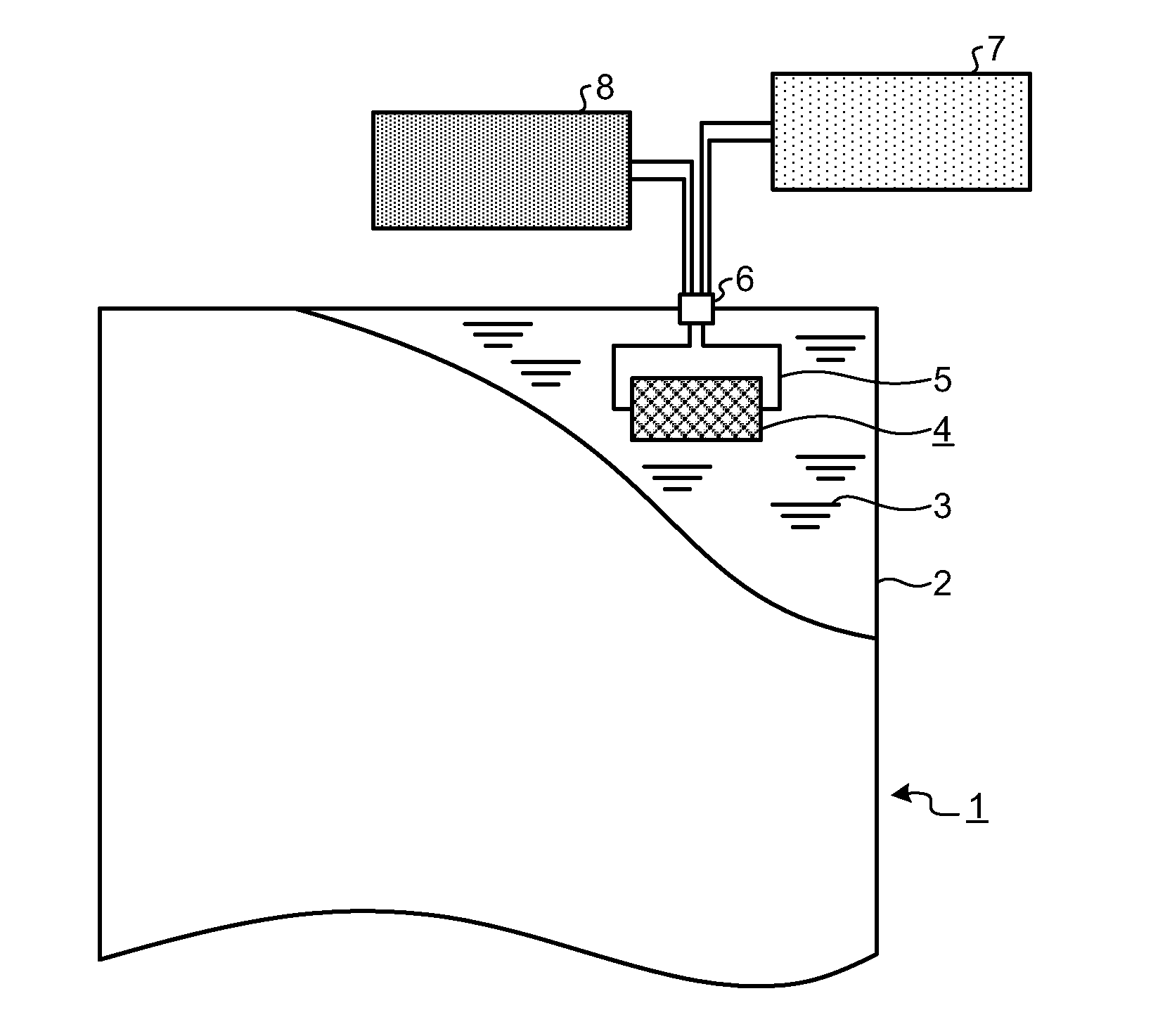
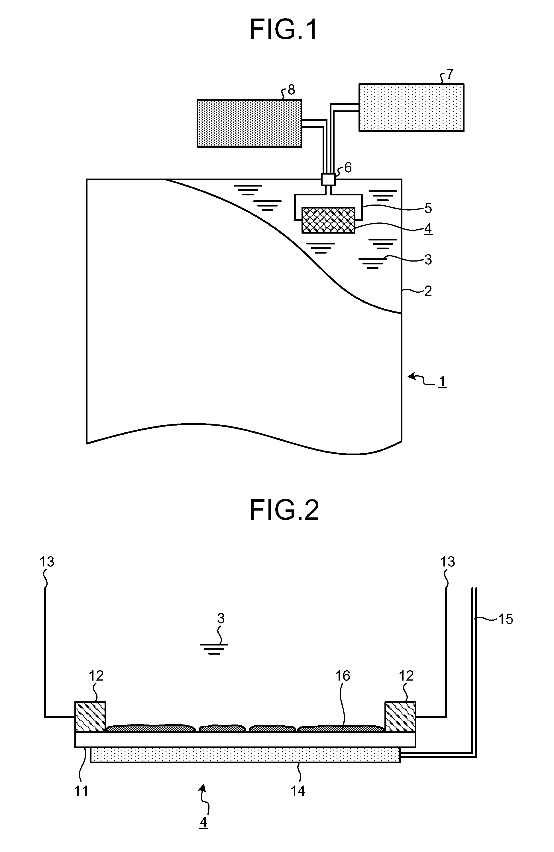
[0035]An oil immersed electrical apparatus according to an embodiment is explained in detail below by using a transformer as an example. FIG. 1 is a diagram of the structure of an oil immersed transformer according to the present embodiment. As illustrated in FIG. 1, an oil immersed transformer 1 includes a tank 2, insulating oil 3, a detection member 4, a lead wire 5, a sealing terminal 6, an insulation resistance tester 7, and a heater controlling device 8.
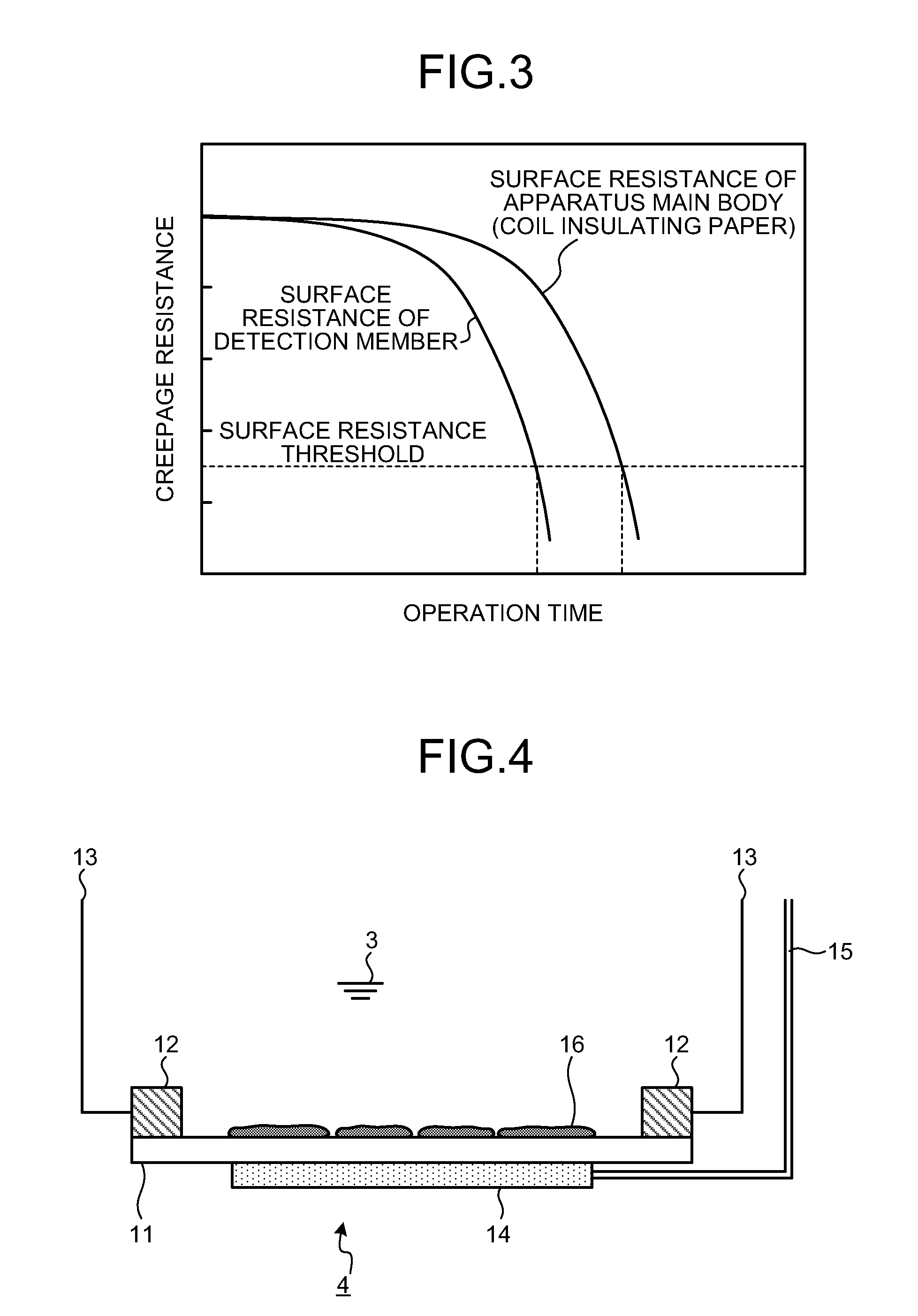
[0036]The oil immersed transformer 1 has a structure such that a not-shown main body of the electrical apparatus, which includes an iron core and a coil wound around the iron core, is housed in the tank 2, and the tank 2 is filled with the insulating oil 3. The not-shown coil is, for example, a copper coil formed of copper, and insulating paper is wound around the copper coil to avoid a short circuit between adjacent turns. In addition, the detection member 4 is also immersed in the insulating oil 3 to detect formation of sulfid...
second embodiment
[0054]FIG. 5 is a diagram of the detailed structure of a detection member according to a second embodiment. The structural components that are the same as those of FIG. 1 are given the same reference numerals. The structure according to this embodiment is such that the electrodes 12 are sandwiched by two pressboards 11 to offer a more reliable detection member 4. In particular, in FIG. 5, two plate-like pressboards 11 are positioned parallel to and opposed to each other, and the two electrodes12 are interposed between these two pressboards 11. Heaters 14 are arranged in contact with the pressboards 11 on the surfaces of the pressboards 11 that are not the surfaces facing each other. The two pressboards 11 are set at the same temperature by the heaters 14. This temperature is set higher than the temperature of the coil unit. In the detection member 4, the two pressboards 11 share the electrodes 12. The properties of the pressboards 11 as solid insulators are the same as the first emb...
third embodiment
[0057]FIG. 6 is a diagram of the detailed structure of a detection member according to a third embodiment. The structural components that are the same as those of FIGS. 1 and 2 are given the same reference numerals. According to the present embodiment, two plate-like pressboards 11 are arranged parallel to and opposed to each other, and two electrodes 12 are arranged at the both ends of the opposing surface of each pressboard. The detection member 4 is configured by interposing insulators 17 between the electrodes 12 arranged on one pressboard 11 and the electrodes 12 on the other pressboard 11. In other words, the two pressboards 11 share the electrodes 12 in FIG. 5, but according to the present embodiment, a pair of electrodes 12 are provided on each of the two pressboards 11 and the insulators 17 are interposed therebetween to insulate the upper and lower pressboards 11 from each other so that the surface resistance between each pair of electrodes 12 can be independently detected...
PUM
| Property | Measurement | Unit |
|---|---|---|
| insulation resistance | aaaaa | aaaaa |
| temperature | aaaaa | aaaaa |
| distance | aaaaa | aaaaa |
Abstract
Description
Claims
Application Information
 - R&D
- Intellectual Property
- Life Sciences
- Materials
- Tech Scout
- Unparalleled Data Quality
- Higher Quality Content
- 60% Fewer Hallucinations
Browse by: Latest US Patents, China's latest patents, Technical Efficacy Thesaurus, Application Domain, Technology Topic, Popular Technical Reports.
© 2025 PatSnap. All rights reserved.Legal|Privacy policy|Modern Slavery Act Transparency Statement|Sitemap|About US| Contact US: help@patsnap.com


