Tool and Method for Rapid Design and Reduction of Rotor Mass

a rotor and mass reduction technology, applied in the field of wind turbine design, can solve the problems of inability to accurately relate the aerodynamic parameters to the rotational dynamic parameters of the rotor blade, the inability to accurately relate the blade mass and the incident wind energy interaction, and the limitations of cfd and other simulation tools, so as to reduce the cost power, improve performance, and reduce the effect of mass per kw

Inactive Publication Date: 2011-04-21
FARIS SADEG M
View PDF15 Cites 5 Cited by
  • Summary
  • Abstract
  • Description
  • Claims
  • Application Information

AI Technical Summary

Benefits of technology

[0038]The local power coefficient, cp(λr), is obtainable from existing successful formulations using well developed tools including computational fluid dynamics models, Blade Element Models, Momentum Theories and other graphical simulation tools. The availability of cp(λr) from these known methods enables the designers to obtain with much less effort the values for the strength integral, Si and the performance integral Pi, without with concerns as to the validity of the models and prior ambiguities. The inventive method enables the designers with less effort to conceive innovative geometries and over all turbine structures that lead to the reduction of cost power ($ / KW) and the cost of energy ($ / MWh).
[0039]The inventive tools and method leading to the precise scaling law manifests its powerful impact in the reduction of mass per KW by factors exceeding 10. The direct consequence the scaling law of the present invention is a newer design trend leading to better performance and lower cost with smaller rotors. This is opposite to the “prevailing wisdom” of the prior art which continues to make larger and larger rotors that weigh hundreds of tons and measure>100 m. By arranging a plurality of smaller rotors, according to the present invention, a novel wind turbine array architecture becomes possible. It comprises an NxNy array of small rotors and an energy accumulator for accumulating energy from the array elements. This is shown to unexpectedly lead to a reduction factor √{square root over (NxNy)} in the mass of the turbine system. For example, Nx=10 and Ny=10, a factor of 10 mass reduction is possible. This method is far more significant, resulting in many fold mass reduction per KW than prior art attempt to avoid or circumvent the fundamental cubic power law, and achieving a mere small fraction of the reduction factor.

Problems solved by technology

Unfortunately, as successful as those simulation tools and models have been, they have not yet succeeded to accurately relate the aerodynamics parameters to the rotational dynamic parameters of the rotor blade.
Most notably the absence of an accurate relation or a link between the blade mass and the aerodynamics interaction with the incident wind energy.
In addition, it employed empirical relationships, extrapolations from data regression, interpretations, intuition and costly computational tools as aids to design and make products.
There are numerous references to discrepancies attributed to the known limitations of CFD and other simulations tools and the scalability issues of the wind tunnel results.
This wide variation amounts to over 100% error.
It cannot be used as a reliable tool for scaling of rotors to different sizes, design optimization and the interpretation of the rotational dynamics behavior.
It may lead to over-design (too conservative) which is costly or to under-design (too aggressive) resulting in catastrophic failures.
They have concluded that although technological barriers could be overcome, it is doubtful whether such large machines are economically viable.
But its volume and weight are proportional to the cube of its dimensions, meaning the price of a turbine climbs faster than its power output as its size increases.
However, there is little basis for mass and costs scaling less than cubically when all variables (especially age of design) are fully taken into account.”
Very large blades may even become practically impossible without further knowledge of the material behavior since the dominating loads on the material are caused by the blade mass.
It is therefore evident from the above, that the issue of blade mass scaling with its radius and the size of exponent has received a great deal of attention and continues to be froth with controversies, uncertainties and discrepancies.
It may also lead to more innovative concepts and rotor configurations heretofore were not possible.

Method used


Image

  • Tool and Method for Rapid Design and Reduction of Rotor Mass
  • Tool and Method for Rapid Design and Reduction of Rotor Mass
  • Tool and Method for Rapid Design and Reduction of Rotor Mass

Examples


second embodiment

[0070]We now show the present invention which is a method and steps to produce mass scaling with respect to strength to weight ratio of the blade material represented by the strength integral Si.

[0071]Step 11: Producing the moment of inertia δIR of the local blade tooth element at point r, to get:

δIR=r2δMR=ρRLδJ   (14)

Where

[0072]L=cfRsinα,

and δJ=δTmr / τs, is the local polar moment of inertia of the blade element at r, δTm is local the maximum allowed torque at r, produced by the maximum wind velocity Vm, at point r, and τs is the shear strength that opposes the maximum torque before a permanent damage results to the blade. Substituting δJ and L in Eq. (14) to relate the local mass element δMR to the maximum torque and the strength of the material, thus:

δMR=ρRRcf sin αδTm / rτs   (15)

[0073]Step 12: Producing the maximum torque element δTm using Eqs. (2) and (3) and setting Vm=rωm / λr to get:

δTm=δPat / ωm=πρ0(cp(r)Vm2r2dr / λrB)   (16)

[0074]Step 12: Producing the blade mass relationship to th...

first embodiment

[0083]The first term 2πρRBPiR3 of Eq. (27) was described according to the

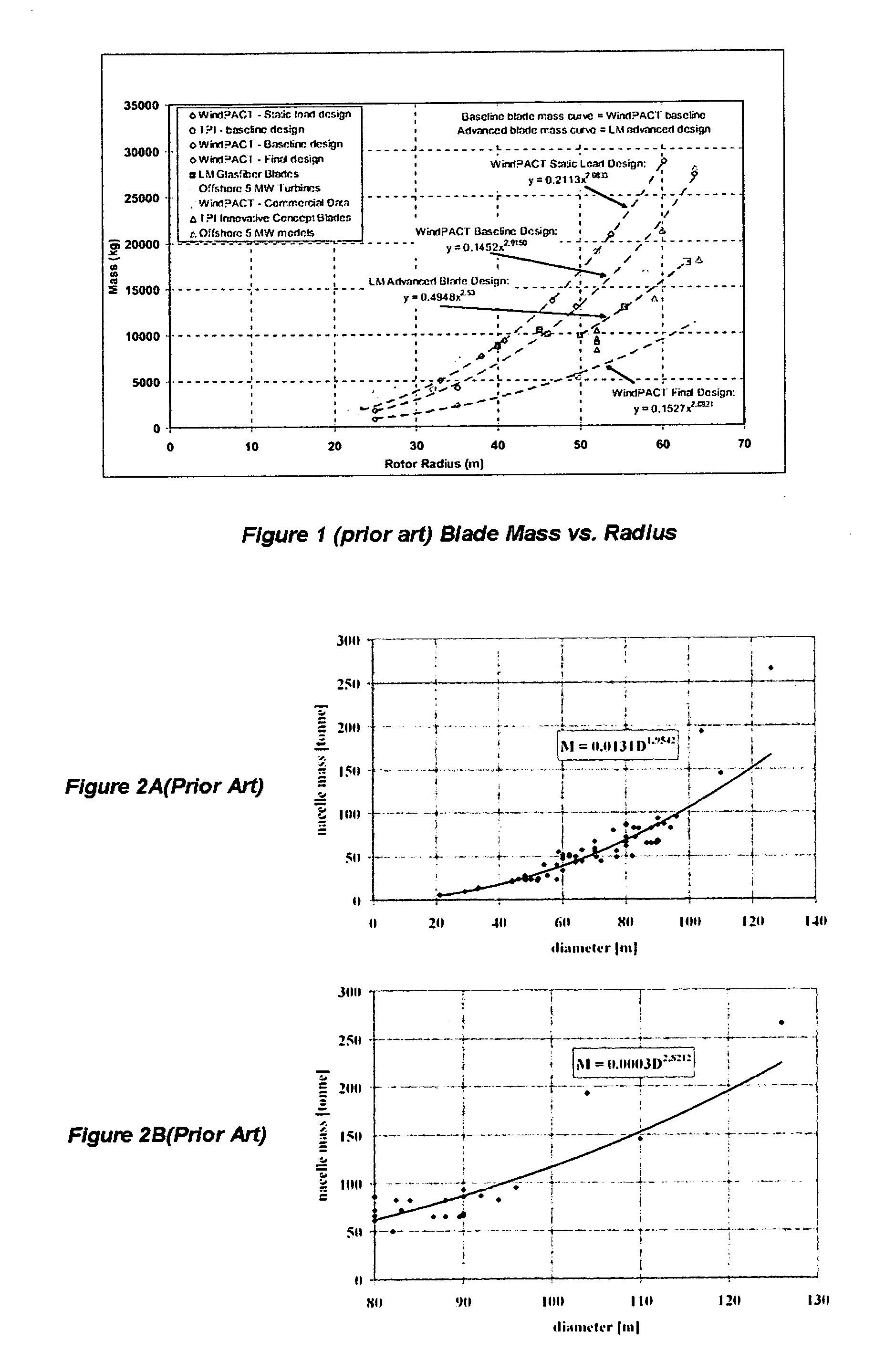
The second term (1+n), is referred to as the Top Head Mass (THM) which is normalized to the rotor mass (2πρRBPiR3) and ranges between 3 for direct drive turbines and 12 in less advanced designs. In absolute mass terms, THM may have values in the range of 50 to 300 ton.

third embodiment

The third term (1+t), is the tower multiplier factor which has values in the range of 1.5-2 and sometimes higher. The fourth term (1+f) is the foundation multiplier factor and has values that range from 2-5, depending on whether the turbine is located on shore, or off-shore. For off-shore locations, (1+t)(1+f) is not only large, but its specific cost / Ton is also very high. According to Eq. (27), it can be seen that the cost of the whole systems is directly related to R3, and the rotor mass has the biggest influence through the multiplier the whole (1+n)(1+t)(1+f) that can range from 12 to 200. For example, a mere 1 ton reduction in the rotor mass leads to a system mass reduction of more than 12 to 200 tons. This influence of the multiplier effect is the basis for this third embodiment which shows that rotor mass reduction of 10× leads a reduction of 100-500× reduction for the whole system for each KW!

[0084]Prior art has pursued advanced architectures aimed at increasing R, but reduc...


PUM

PropertyMeasurementUnit
massaaaaaaaaaa
radiusaaaaaaaaaa
mass MRaaaaaaaaaa

Abstract

Wind turbine rotors are designed by means of computationally intensive algorithms, simulation tools and various models. These art methods, however, have not been successful in relating the blade mass directly to the aerodynamic, rotational dynamics and material parameters. Consequently, modelers are often grappling with discrepancies and ambiguities. Prior art generally constructs the empirical relation MR∝Rν where ν is given a value that ranges between 1.8 and 3, depending on who, and how the experimental data is presented and compared with theoretical or simulation results. The present invention derives for the first time a precise scaling law that relates the blade mass to the cubic power of R exactly. It is based on using a novel tool in the form of a set virtual air gear teeth that intermesh with the blade gear teeth, to link the actuator disc to the rotational dynamics and material properties of the blades.

Description

CROSS-REFERENCE TO RELATED APPLICATIONS[0001]This application claims the benefit of provisional patent application Ser. No. 61 / 252,696, filed on Oct. 18, 2009, incorporated herein by reference in its entirety.FIELD OF THE INVENTION[0002]This invention is related to the design of wind turbines for harvesting and using wind power. More specifically, it is related to design tools, methodologies, and scaling laws that enable the prediction with precision the performance and cost of components and systems. Even more specifically, it is related to how the rotor blade mass is directly and accurately linked to the aerodynamic parameters resulting from the blade structure interaction with the wind energy. It is related to the recognition that the mass cubic power law is powerful tool for drastic mass reduction per unit power in the embodiments of rotor array architectures.BACKGROUND OF THE INVENTION[0003]Newton's Laws of motion govern our environment and many aspects of our lives. Forces act...

Claims


Application Information

Patent Timeline
Patent Type & Authority Applications(United States)
IPC IPC(8): F03D11/00B23P15/02B23P19/00
CPCF03D1/0666F05B2200/222Y10T29/49336Y10T29/53Y02E10/721Y02E10/72F03D1/0658
Inventor FARIS, SADEG M.
Owner FARIS SADEG M
Why Eureka
Try Eureka