Ultra-thin co2 selective zeolite membrane for co2 separation from post-combustion flue gas

a zeolite membrane and co2 separation technology, applied in the field of ultra-thin co2 selective zeolite membranes for co2 separation from post-combustion flue gas, can solve the problems of limited flue gas application, ineffective condensation of cosub>2 /sub>, and the cost of capturing cosub>2 /sub>using gas-separation membranes is only about 65% of the cost using a pressurized

Inactive Publication Date: 2011-04-28
GAS TECH INST
View PDF6 Cites 19 Cited by
  • Summary
  • Abstract
  • Description
  • Claims
  • Application Information

AI Technical Summary

Benefits of technology

[0011]This invention provides methods for making crystalline silicoaluminophosphate (SAPO) membranes on a porous support. Inorganic membranes such as SAPOs can have superior thermal, mechanical and chemical stability, good erosion resistance, and high pressure stability as compared with conventional polymeric membranes. The methods of this invention can produce SAPO membranes and, in particular, SAPO-34 membranes, having improved CO2 / N2 selectivities as compared with conventional membranes and which are capable of separating CO2 from post-combustion flue gas.
[0016]4) Post-synthesis treatment—To tailor pore structure, membrane is post-treated (for example, by using chemical layer deposition) to systematically reduce the zeolite and possible non-zeolite pore sizes, thereby further decreasing the diffusivity of N2 and, thus, increasing CO2 / N2 selectivity.

Problems solved by technology

However, with atmospheric pressure flue gases, CO2 cannot be effectively condensed.
Creating this driving force accounts for most of the cost for membrane separation since flue gases are at or slightly above atmospheric pressure.
Using this mode, it has been estimated that the cost of capturing CO2 using gas-separation membranes is only about 65% of the cost using a pressurized feed.
However, they have limitations for flue gas application because of their poor performance, stability at high temperature, and their intolerance to harsh chemicals.
Although flue gases can be cooled prior to a separation, the associated energy consumption increases the cost.

Method used


Image

  • Ultra-thin co2 selective zeolite membrane for co2 separation from post-combustion flue gas
  • Ultra-thin co2 selective zeolite membrane for co2 separation from post-combustion flue gas
  • Ultra-thin co2 selective zeolite membrane for co2 separation from post-combustion flue gas

Examples


Embodiment Construction

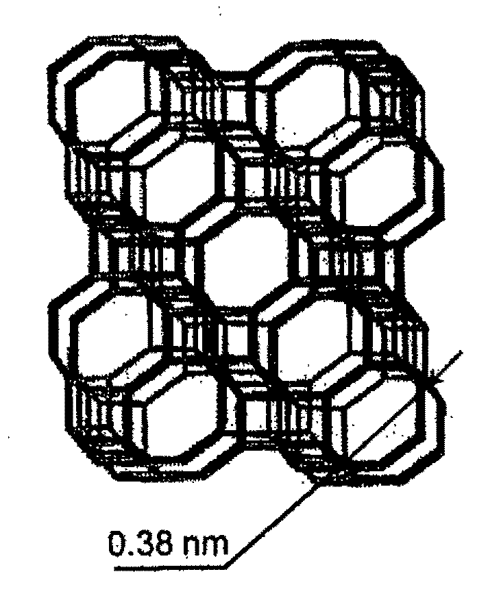
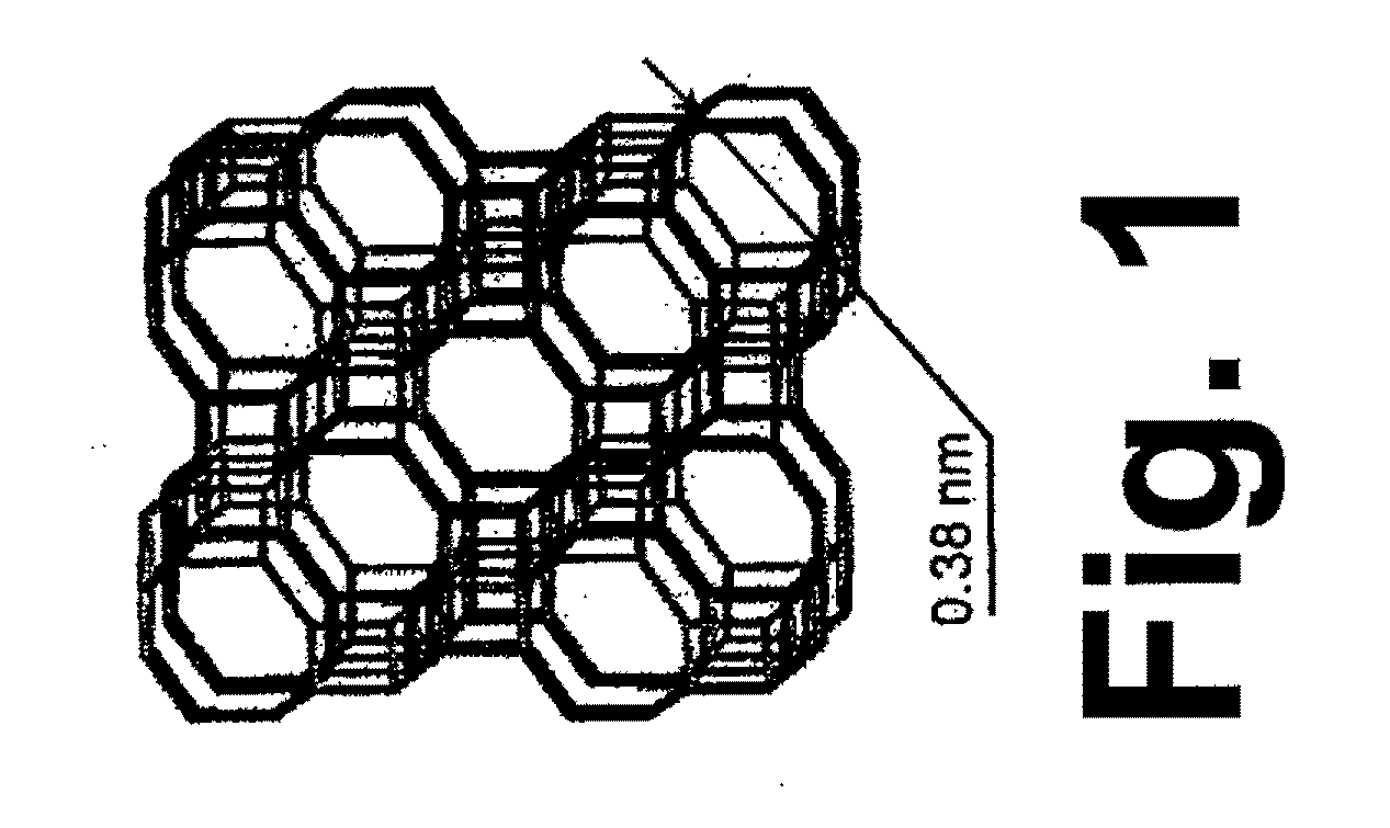
[0029]SAPO-34 membranes, synthesized on porous α-Al2O3 supports by using multiple templates and reduced crystallization time in accordance with one embodiment of the method of this invention, show high CO2 permeability for separating CO2 / N2 mixtures up to 230° C. At a trans-membrane pressure drop of 138 kPa and an atmospheric pressure on the permeate side, one such membrane had a CO2 permeance of 1.2×10⁻⁶ mol / (m2·s·Pa) (=3,500 GPU) with a CO2 / N2 separation selectivity of 32 for a 50 / 50 feed at 22° C. At a feed pressure of 23 bar, the CO2 flux was as high as 75 kg / (m2·h). CO2 / N2 separations were investigated in part by using vacuum permeate pumping, whereby the membrane showed a CO2 permeance of 7.7×10⁻⁷ mol / (m2·s·Pa) and a CO2 permeate concentration of 93% for an equimolar feed at 22° C. For a 10% CO2 / 90% N2 feed, to reach a CO2 permeate concentration of 99%, only three steps were required at 22° C. and 4 steps required at 110° C.

[0030]The membranes of this invention are formed by c...


PUM

PropertyMeasurementUnit
pore sizeaaaaaaaaaa
sizeaaaaaaaaaa
thicknessaaaaaaaaaa

Abstract

A method for producing a crystalline silicoaluminophosphate (SAPO) membrane in which a porous support is contacted with SAPO seed crystals to form a SAPO seeded porous support. The SAPO seeded porous support is filled with an aqueous SAPO synthesis gel including a mixture of sources of aluminum, phosphorus, silicon, oxygen, water, and a templating agent, forming a gel-filled porous structure which is then heated to form a SAPO layer of SAPO crystals on a surface of and / or within pores of the porous support. The SAPO layer is calcined, thereby removing the templating agent and forming a supported porous SAPO membrane layer, which is then subjected to a pore size reduction post-synthesis treatment process, producing a reduced pore size supported porous SAPO membrane layer having an average pore size of less than about 0.38 nm.

Description

BACKGROUND OF THE INVENTION[0001]1. Field of the Invention[0002]This invention relates to silicoaluminophosphate (SAPO) membranes. More particularly, this invention relates to SAPO membranes supported on porous supports. This invention further relates to SAPO membranes for selective separation of gases in a gas mixture. This invention further relates to supported SAPO membranes and methods for producing such membranes.[0003]2. Description of Related Art[0004]One of the more significant contributors to global warming is the emission of greenhouse gases, particularly carbon dioxide (CO2), into the atmosphere. The primary sources of CO2 emissions are fossil fuel combustion, natural gas sweetening, synthesis gas production and certain chemical plants. The United States is committed to reducing the greenhouse gas intensity of the American economy by 18% over the 10-year period from 2002 to 2012.[0005]Low-temperature distillation is a widely used commercial process for purification and li...

Claims


Application Information

Patent Timeline
Patent Type & Authority Applications(United States)
IPC IPC(8): B01D53/22C01B39/02B01J29/06B01J29/072
CPCB01D53/228B01D67/0051B01D69/10B01D71/028B01J29/06B01J29/072B01D2325/04B01D67/0083B01D67/0093B01D2323/08B01D2323/24B01D2323/283Y02C10/10Y02C20/40
Inventor LI, SHIGUANGFAN, QINBAI
Owner GAS TECH INST
Why Eureka
Try Eureka