Joining method of dissimilar metal plates and dissimilar metal joined body

a technology of metal plates and metal joints, which is applied in the field of joining methods of dissimilar metal plates and dissimilar metal joints, can solve the problems of insufficient welding current, inability to increase the welding current sufficiently, and inability to obtain sufficient joint strength, etc., and achieve the effect of improving joint strength

Active Publication Date: 2011-04-28
MAZDA MOTOR CORP +1
View PDF5 Cites 42 Cited by
  • Summary
  • Abstract
  • Description
  • Claims
  • Application Information

AI Technical Summary

Benefits of technology

[0011]The present invention was devised in view of the foregoing circumstances. Thus, an object of this invention is to effectively improve the joint strength upon joining dissimilar metal plates by combining adhesion using an adhesive and spot welding.

Problems solved by technology

Nevertheless, with a product such as an automobile that is used under a severe corrosion environment, if the steel plate and the aluminum alloy plate are directly joined, there is a problem in that corrosion (electrolytic corrosion) caused by the potential difference between the two occurs easily.
However, since an adhesive has inferior conductivity and will cause an increase in the conduction resistance during the spot welding process, it is not possible to increase the welding current sufficiently.
Moreover, since the cleanliness factor of the interface of the steel plate and the aluminum alloy plate is also aggravated, there is a problem in that, consequently, sufficient joint strength cannot be obtained.
However, if the tip of the electrode is formed in a convex curved surface, although the adhesive of the portion corresponding to the apex of such convex curved surface will be discharged reliably, the adhesive will only be discharged locally, and, as a result of the joint area of the steel plate and the aluminum alloy plate becoming small, there is a possibility that sufficient joint strength cannot be obtained.
Moreover, although Japanese Unexamined Patent Application Publication No. 2008-23583 also proposes heating the vicinity of the joint part using an external heating means configured from a high frequency coil or the like in order to facilitate the discharge of the adhesive, there is a possibility that the temperature of the adhesive of the joint part may not be effectively increased due to the influence of the thermal conduction to the periphery thereof.
Nevertheless, if the metal plates are joined in a state where such a thermoplastic resin spacer is interposed therebetween, there is a possibility that the thermoplastic resin spacer will melt and flow to the outside, for example, when the obtained joined body is coated and subject to thermal treatment in the subsequent drying step.
If resin flows out as described above, the sealability of the joint part will be lost, and, in particular, this will become a crucial defect as a structural material of a vehicle body.

Method used


Image

  • Joining method of dissimilar metal plates and dissimilar metal joined body
  • Joining method of dissimilar metal plates and dissimilar metal joined body
  • Joining method of dissimilar metal plates and dissimilar metal joined body

Examples


example 1

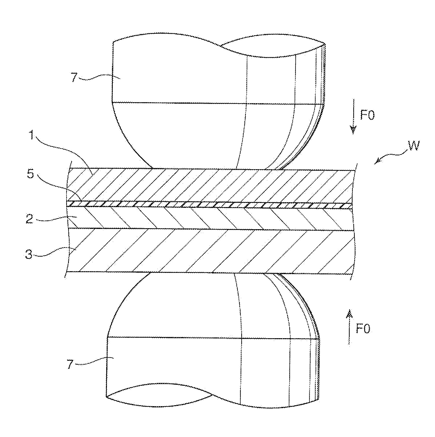
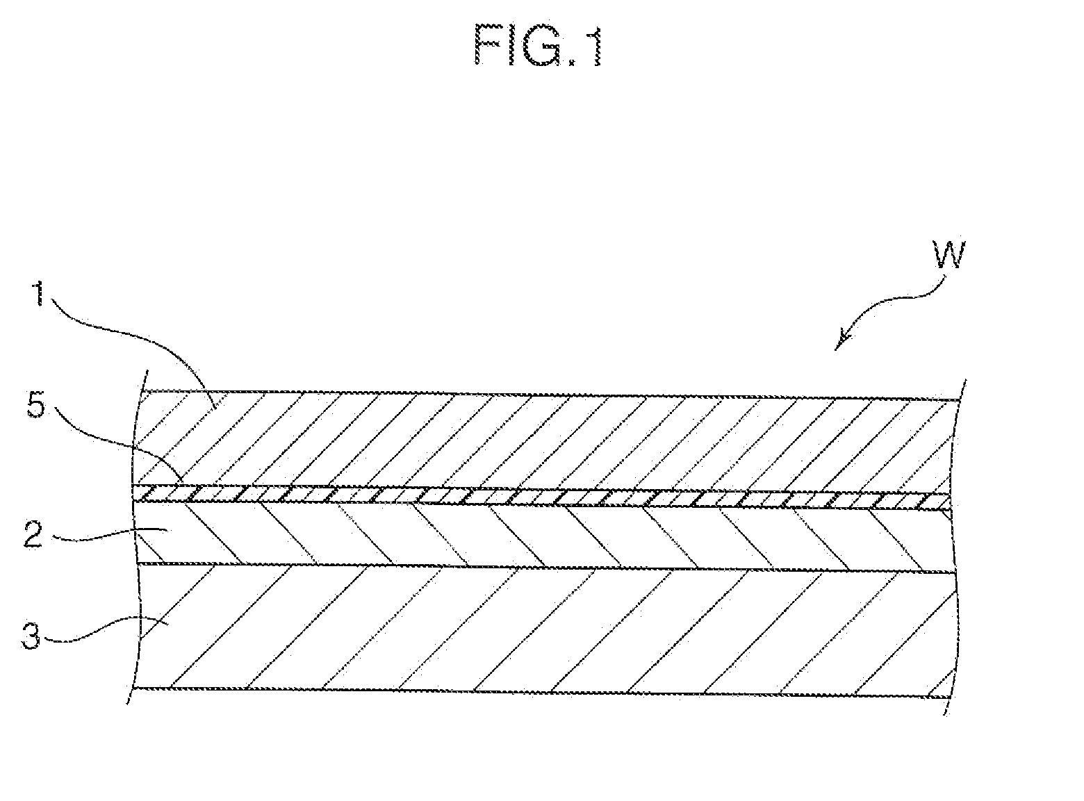
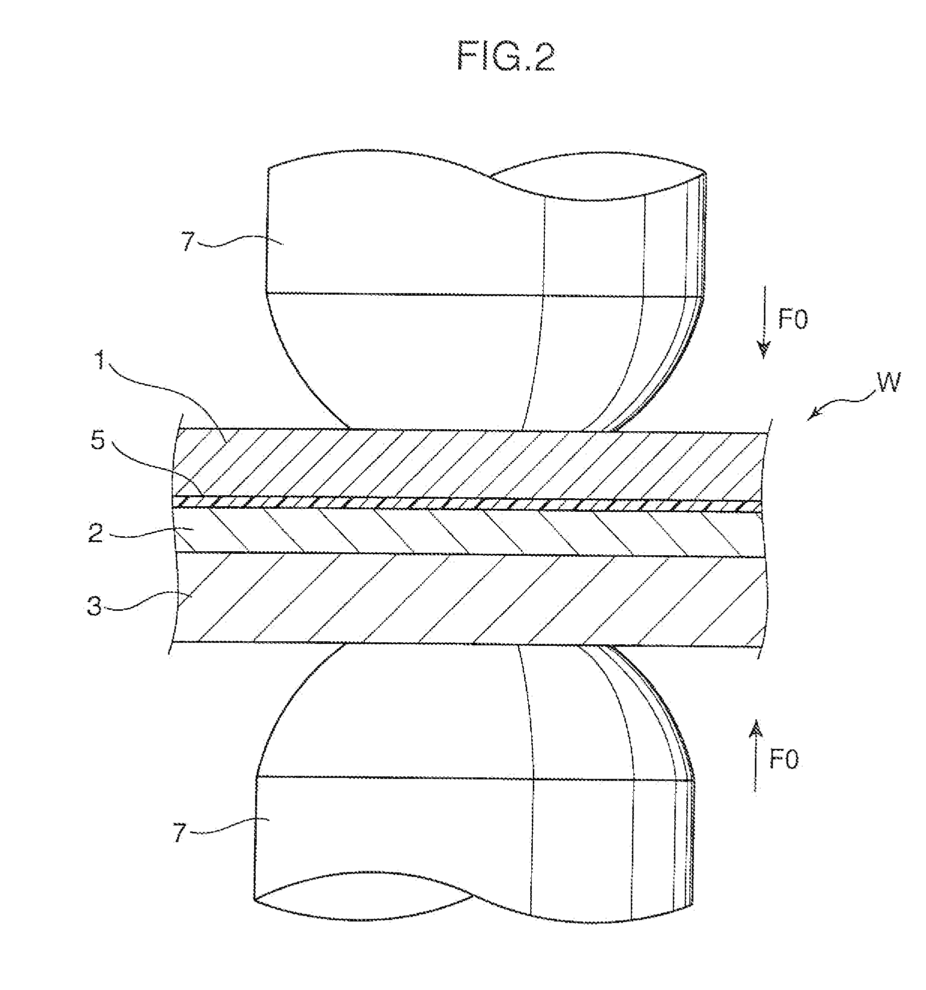
[0074]The joining conditions of Example 1 are as shown in FIG. 10 and FIG. 11. In other words, in Example 1, foremost, as the pre-pressurization step, a pressing force of 2 kN is applied for 60 cyc (1000 msec). Subsequently, as the pre-heating step, while continuing the pressurization at 2 kN, a current of 2 kA is applied for 15 cyc (250 msec). Subsequently, as the cooling step, a pressing force of 7 kN is applied for 60 cyc (1000 msec) in a state where the conduction is stopped. Finally, as the welding step, while continuing the pressurization at 7 kN, a current of 14 kA is applied for 18 cyc (300 msec). Note that, in this Example, the type 1 electrode (FIG. 8A) was used as the electrode 7 on the aluminum side (side to come in contact with the aluminum alloy plate 1), and the type 1 electrode was also used as the electrode 7 on the steel plate side (side to come in contact with the non-plated steel plate 3).

example 2

[0075]In Example 2, foremost, as the pre-pressurization step, a pressing force of 2 kN is applied for 60 cyc (1000 msec). Subsequently, as the pre-heating step, a current of 2 kA is applied for 15 cyc (250 msec). Here, while the pressing force is set to 2 kN for 10 cyc (167 msec) from the start of the pre-heating step, the pressing force is set to 7 kN for the subsequent 5 cyc (83 msec). Subsequently, as the cooling step, a pressing force of 7 kN is applied for 60 cyc (1000 msec) in a state where the conduction is stopped. Finally, as the welding step, while continuing the pressing force of 7 kN, a current of 14 kA is applied for 18 cyc (300 msec). Note that the electrode 7 that is used in this Example is the type 1 electrode (FIG. 8A) for both the aluminum side and the steel plate side.

example 3

[0076]With respect to the joining conditions of Example 3, although the timing of pressurization and conduction is the same as Example 1, what is different from Example 1 is that the pressing force during the cooling step and the welding step is set to 5 kN, and the conduction current during the welding step is set to 13 kA. Note that the electrode 7 that is used in this Example is the type 1 electrode (FIG. 8A) for both the aluminum side and the steel plate side.


PUM

PropertyMeasurementUnit
thicknessaaaaaaaaaa
thicknessaaaaaaaaaa
currentaaaaaaaaaa

Abstract

The joining method of the present invention includes a lapping step of lapping the aluminum alloy plate (1) and the plated steel plate (2) via the adhesive (5), a pre-heating step of clamping both of the metal plates (1, 2) that have been lapped in the lapping step between a pair of electrodes (7, 7) for spot welding and applying pressure thereto, and applying a current between the pair of electrodes (7, 7), a cooling step of pressurizing, after the pre-heating step, both of the metal plates (1, 2) at a pressing force which is higher than that at the start of the pre-heating step in a state where conduction between the electrodes (7, 7) is stopped, and continuing this pressurization over a predetermined cooling time, and a welding step of pressurizing, after the cooling step, both of the metal plates (1, 2) at a pressing force which is higher than that at the start of the pre-heating step, and welding both of the metal plates (1, 2) by applying a current which is higher than the conduction current value in the pre-heating step between the pair of electrodes (7, 7). It is thereby possible to firmly join the dissimilar metal plates (1, 2) by combining adhesion due to an adhesive and spot welding.

Description

BACKGROUND OF THE INVENTION[0001]1. Field of the Invention[0002]The present invention relates to a method of joining dissimilar metal plates of an aluminum alloy plate and a plated steel plate by means of adhesion of an adhesive and spot welding, and the like.[0003]2. Description of the Background Art[0004]Conventionally, in the fields of transport equipment such as automobiles and rail cars, machine parts, architectural buildings and the like, research and development concerning methods of joining dissimilar metals such as, for example, a steel material and aluminum alloy, and a joined body of such dissimilar metals.[0005]In particular, in the field of automobiles, there is further demand of achieving the weight-saving of the vehicle body in light of the severe energy situation in recent years, and light-weight aluminum alloy plate materials are often used together with steel plates. Nevertheless, with a product such as an automobile that is used under a severe corrosion environmen...

Claims


Application Information

Patent Timeline
Patent Type & Authority Applications(United States)
IPC IPC(8): B32B15/01B23K11/11
CPCB23K11/115B23K11/166B23K11/185B23K11/20B23K11/24Y10T428/12347B23K2201/18B23K2201/34B23K2203/20C09J5/10C09J2400/163B23K2201/006B23K2101/006B23K2101/18B23K2101/34B23K2103/20
Inventor TANAKA, KOUJIROUNISHIGUCHI, KATSUYASASABE, SEIJI
Owner MAZDA MOTOR CORP
Why Eureka
Try Eureka