Differential signal transmission cable
- Summary
- Abstract
- Description
- Claims
- Application Information
AI Technical Summary
Benefits of technology
Problems solved by technology
Method used
Image

Examples
first embodiment
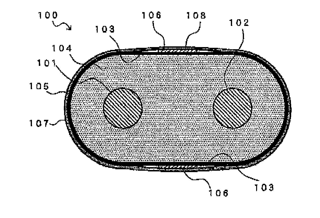
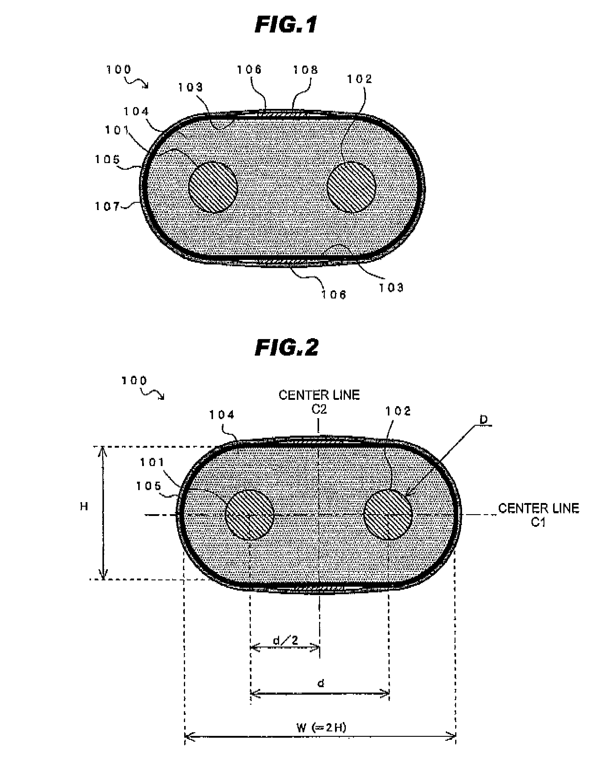
[0090]FIG. 1 is a cross-sectional view of a differential signal transmission cable in the first embodiment according to the present invention.
[0091]Referring to FIG. 1, a differential signal transmission cable 100 in the first embodiment according to the present invention comprises two conductor wires 101, 102 disposed to be parallel with each other, a flat insulating member 104 collectively covering the two conductor wires 101, 102, the insulating member 104 having flat portions 103 facing to each other in a direction perpendicular (vertical direction in FIG. 1) to an alignment direction (horizontal direction in FIG. 1) of the two conductor wires 101, 102 to sandwich the two conductor wires 101, 102, a shield conductor 105 comprising a metal foil tape and being wound around an outer periphery of the insulating member 104, a drain wire 106 provided to contact with the shield conductor 105 at a position corresponding to the flat portions 103, and a jacket 107 jacketing the drain wire...
examples
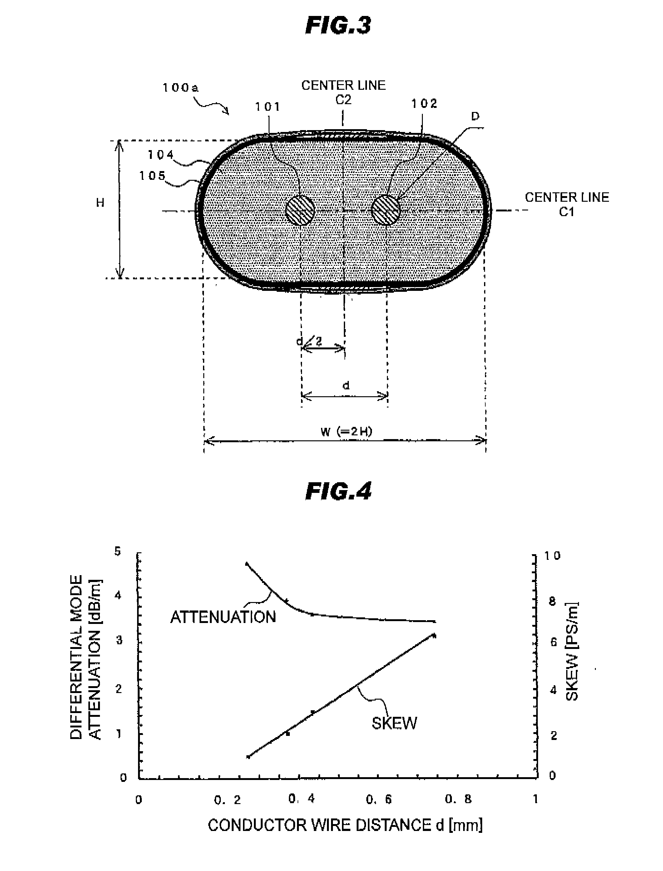
[0123]For the purpose of confirming the above contemplation, several kinds of samples of the differential signal transmission cable 100a as shown in FIG. 3 were prepared. In the samples, the diameter D of the conductor wires 101, 102 and the distance d between the conductor wires 101, 102 were changed in such a manner that the differential mode impedance is 100Ω. Characteristics of the respective samples were evaluated as follows. The height H of the insulating member 104 was 0.74 mm and the width W was 1.48 mm. As the insulating member 104, perfluoroalkoxy (PFA with a specific dielectric constant of 2.1) was used. A 4-port network analyzer was used for analysis of the transmission loss. A TDR (Time Domain Reflectometry) measuring apparatus using a pulse signal with a rising time (leading-edge time) of 35 ps was used for analysis of the skew.
[0124]TABLE 1 shows a measurement result of the common mode impedance when conductor wire 101 in FIG. 3, the diameter D of the conductor wires ...
second embodiment
[0129]FIG. 5 is a cross-sectional view of a differential signal transmission cable 500 in the second embodiment according to the present invention.
[0130]Referring to FIG. 5, similarly to the differential signal transmission cable 100 of FIG. 1, a differential signal transmission cable 500 in the second embodiment according to the present invention comprises two conductor wires 501, 502 disposed to be parallel with each other, a flat insulating member 504 collectively covering the two conductor wires 501, 502, the insulating member 504 having flat portions 503 and having a flat cross section, a shield conductor 505 wound around an outer periphery of the insulating member 504, and a drain wire 506 provided at an outer periphery of the shield conductor 505 to contact with the shield conductor 505.
[0131]The second embodiment is similar to the first embodiment except the drain wire 506. As the drain wire 506, an FFC (Flexible Flat Cable) 510 with a configuration, in which a rectangular w...
PUM
 Abstract
Description
Claims
Application Information
 - Generate Ideas
- Intellectual Property
- Life Sciences
- Materials
- Tech Scout
- Unparalleled Data Quality
- Higher Quality Content
- 60% Fewer Hallucinations
Browse by: Latest US Patents, China's latest patents, Technical Efficacy Thesaurus, Application Domain, Technology Topic, Popular Technical Reports.
© 2025 PatSnap. All rights reserved.Legal|Privacy policy|Modern Slavery Act Transparency Statement|Sitemap|About US| Contact US: help@patsnap.com