LED lamp

a technology of led lamps and led lamps, applied in the field of led lamps, can solve the problems of reducing the life of led lamps, affecting the efficiency of LED lamps, and deteriorating illuminance, and achieves the effects of enhancing the surface heat dissipation constant, high radiation emission rate, and sufficient heat dissipation performan

Inactive Publication Date: 2011-05-05
YOO YOUNG HO +1
View PDF18 Cites 122 Cited by
  • Summary
  • Abstract
  • Description
  • Claims
  • Application Information

AI Technical Summary

Benefits of technology

[0031]The present invention has the following effects:
[0032]First, the lamp has therein a heat dissipation transfer member so that heat generated from the LEDs while the LEDs are on can be diffused and transferred rapidly to the entire area of the power source base or the floodlight cover, and the power source base is made of materials including polycarbonate, etc with a high emission rate of radiation so as to enhance its surface heat dissipation constant. In this manner, the power source base has sufficient heat dissipation performance even though it is made of an insulation material and, hence, a separate insulation circuit is not necessary, which improves the reliability and productivity of the lamp and reduces the cost of manufacturing.
[0033]Second, as the light guiding type floodlight cover guides and diffuses light from the LED lamp so as to emit the light uniformly over the entire outer surface including the peripheral region of the lamp, the lamp can provide uniform illuminance over the entire region and high brightness without glare, thereby improving the quality of illumination remarkably.
[0034]Third, the lamp includes a vertical ventilation channel for heat dissipation, which produces a stack effect by the temperature difference between air at normal temperature flowing from the lower external space to the lamp and upward-moving air heated through exchanging heat with the PCB within the lamp, and consequent difference in lifting power and pressure. By the stack effect, warm air within the lamp rises rapidly and is discharged out of the lamp, and accordingly, the heat dissipation performance is improved markedly.
[0035]Fourth, as the lamp employs a power control unit integrating an optical source part in which both the power control unit and LEDs (light source) are mounted onto the same PCB, the expense of PCB equipment is reduced by about a half and, furthermore, a connector and the connecting process are not necessary, thereby reducing the cost of manufacturing markedly and minimizing defects.

Problems solved by technology

Accordingly, if heat is generated while the lamp is on, the generated heat does not dissipate properly and, as a result, its illuminance deteriorates rapidly and its lifetime is also shortened remarkably.
the separate insulation circuit including primary and secondary coils must be included in the LED driving circuit, and the addition of the electronic devices makes the configuration of the LED driving circuit complicated and increases the manufacturing cost of the lamp.
In that case, heat dissipation efficiency is relatively low compared to the cost of manufacturing (see Table 1).
On the other hand, in case the power source base is made of an insulation material, the insulation material has low thermal conductivity and moreover, as mentioned above, heat is transferred to the power source base only through the limited area in which the PCB and one end of the power source base contact each other and, as a result, heat transfer between the power source base and the PCB as well as heat diffusion and dissipation through the entire outer surface of the power source base is delayed.
Consequently, the heat dissipation performance of the lamp becomes poor, and this results in low illuminance and short lifetime.
These properties make a large difference in illuminance between the center directly under the lamp and its peripheral region, and lower the quality of illumination considerably.
That is, in an incandescent lamp, the difference in illuminance between the center and the peripheral region is small, whereas in this prior art LED lamp, light from LED focuses on the central region and therefore the center is excessively bright and glaring but the peripheral region is much darker.
However, those approaches lower the illuminance.
Moreover, as LED is driven by a low DC voltage, a high voltage or AC voltage can damage it.
Then, in order to interconnect the two PCBs electrically, a wire and a connector are required, which increases the cost of materials.
Furthermore, there should be a plurality of assembling steps, resulting in the increase of the manufacturing cost.
Moreover, as the LED optical source and the power control unit are disposed as two discrete units, thereby forming complex configuration, defects may occur at the connecting process for electrically connecting the two units and productivity goes down.

Method used


Image

  • LED lamp
  • LED lamp
  • LED lamp

Examples


Embodiment Construction

[0052]Exemplary embodiments of the present invention will be described with reference to the accompanying drawings.

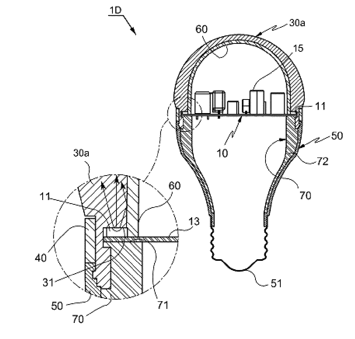
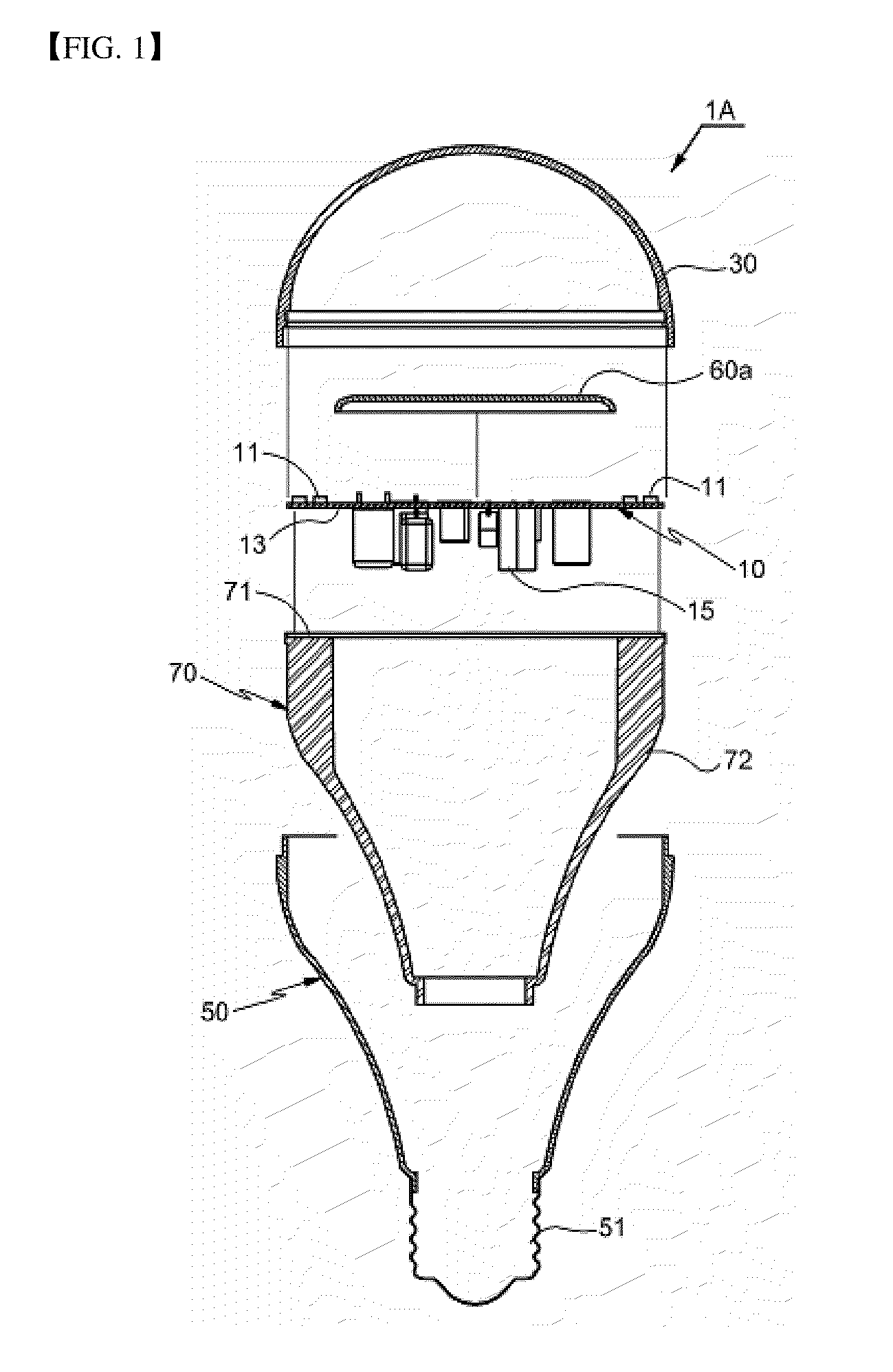
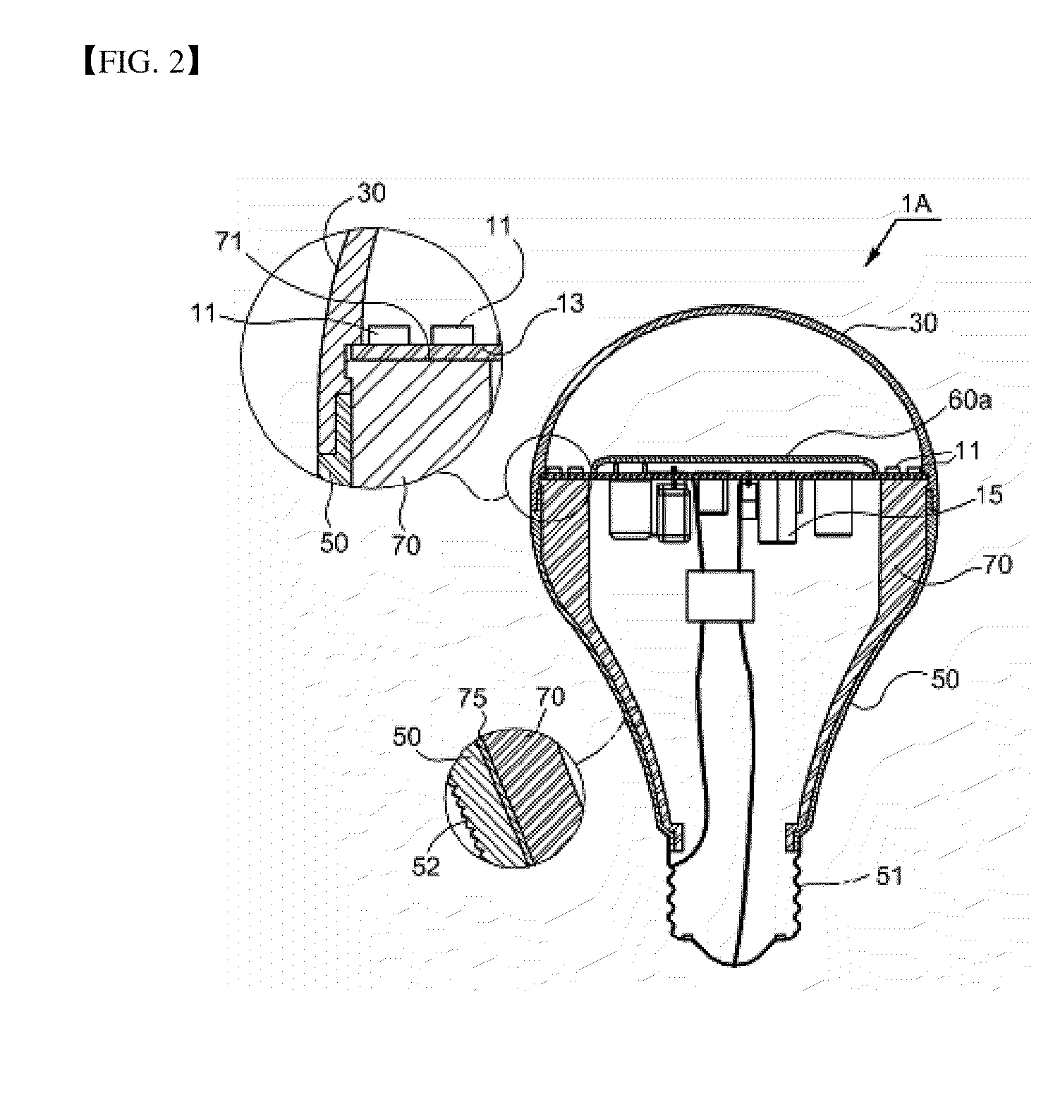
[0053]FIG. 1 shows a cross-sectional view of the disassembled parts of an LED lamp according to one exemplary embodiment of the present invention, and FIG. 2 shows a cross-sectional view of the assembled LED lamp of FIG. 1.

[0054]As shown in FIG. 1 and FIG. 2, LED lamp 1A according to the first exemplary embodiment of the present invention comprises one or more LEDs 11 mounted on the PCB 13, a floodlight cover 30 that transmits light from the LEDs 11, and a power source base 50 coupled to the floodlight cover 30 and having a terminal 51 at one end thereof. The power source base 50 is made of an insulation material, and lamp 1A further comprises a heat dissipation transfer member 70 which includes a heat sink 71 and a main body 72 formed and installed so as to overlap with and be in tight contact with the inner side of either the power source base 50 or the floodlight cov...


PUM


Abstract

The present invention relates to an LED lamp in which, because the lamp has therein a heat dissipation transfer member and the power source base thereof is made of materials including polycarbonate, etc. with a high emission rate of radiation so as to enhance its surface heat dissipation constant, the power source base has sufficient heat dissipation performance and, thus, a separate insulation circuit is not necessary, thereby improving reliability and productivity of the lamp as well as reducing the cost of manufacturing.
To this end, the present invention provides an LED lamp comprising one or more LEDs mounted on a PCB, a floodlight cover that transmits light from the LEDs, and a power source base coupled to the floodlight cover and having a terminal at one end thereof, wherein the power source base is made of an insulation material; and the LED lamp also comprises a heat dissipation transfer member that has a heat sink in contact with the PCB on which the LEDs are mounted, and is formed and installed so as to overlap with and be in tight contact with the inner face of either the power source base or the floodlight cover or both.

Description

CROSS-REFERENCE TO RELATED APPLICATIONS[0001]This application is based upon and claims the priorities from prior Korean patent Application No. 2009-0104139 filed on Oct. 30, 2009, prior Korean patent Application No. 2009-0105847 filed on Nov. 4, 2009 and prior Korean patent Application No. 2009-0126522 filed on Dec. 18, 2009, the entire contents of which are incorporated herein by reference.BACKGROUND OF THE INVENTION[0002]1. Field of the Invention[0003]The present invention relates to an LED lamp in which, because the lamp has therein a heat dissipation transfer member and the power source base thereof is made of materials including polycarbonate, etc. with a high emission rate of radiation so as to enhance its surface heat dissipation constant, the power source base has sufficient heat dissipation performance and, thus, a separate insulation circuit is not necessary, thereby improving reliability and productivity of the lamp as well as reducing the cost of manufacturing.[0004]The ...

Claims


Application Information

Patent Timeline
Patent Type & Authority Applications(United States)
IPC IPC(8): H01J13/46H01J61/52
CPCF21K9/135F21K9/52F21V3/02F21V23/005F21Y2101/02F21V29/87F21V29/506F21V29/70F21V29/74F21V29/83F21V29/505F21K9/232F21K9/61F21Y2115/10F21K9/238F21Y2103/33F21V29/507F21V3/04F21V17/10F21V23/02Y10S362/80
Inventor YOO, YOUNG HO
Owner YOO YOUNG HO
Why Eureka
Try Eureka