Liquid Crystal Displays with Embedded Photovoltaic Cells

a technology of photovoltaic cells and liquid crystal displays, which is applied in the manufacture of electrode systems, electric discharge tubes/lamps, instruments, etc., can solve the problems of insufficient color saturation, low contrast ratio, and inability to meet the increasing demand of users, and achieves the effect of long working time and high energy efficiency

Inactive Publication Date: 2011-05-12
UNIV OF CENT FLORIDA RES FOUND INC +1
View PDF8 Cites 32 Cited by
  • Summary
  • Abstract
  • Description
  • Claims
  • Application Information

AI Technical Summary

Benefits of technology

[0013]A primary objective of the invention is to provide devices and methods for a LCD with photovoltaic cells that can have a high energy efficiency, which could make the display device a longer working time than conventional displays without PV cells.

Problems solved by technology

However, typical reflective LCDs usually have low contrast ratio (resulting from the surface reflection) and insufficient color saturation, which cannot meet the increasing demand of users.
However, the following drawbacks of a pure transmissive LCD are evident: 1) its power consumption is high, resulting from the dependence of a backlight, and 2) its image is easily washed out by strong outdoor sunlight, as its output light cannot compete with the ambient light there.
However, the power consumption is reduced in a way that sacrifices the transmissive region that has a high image quality.
However, several problems still exist: 1) the image quality like contrast and color saturation of this device is low since a PDLC based reflective typed LCD is employed, which limits its application, and 2) the PV cell 13 is not transparent to the whole visible spectrum, in other words, the image color of the display is deteriorated by the color the PV cell as well.
However, several problems exist.
Second, the majority of the charging is accomplished when the transflector is working under a transmissive mode.
Besides, the light to charge the PV cell is from the ambient lights, while the input efficiency (the amount of light coming to the PV cell surface) is usually low.

Method used


Image

  • Liquid Crystal Displays with Embedded Photovoltaic Cells
  • Liquid Crystal Displays with Embedded Photovoltaic Cells
  • Liquid Crystal Displays with Embedded Photovoltaic Cells

Examples


Embodiment Construction

[0032]Before explaining the disclosed embodiments of the present invention in detail, it is to be understood that the invention is not limited in its application to the details of the particular arrangements shown since the invention is capable of other embodiments. Also, the terminology used herein is for the purpose of description and not of limitation.

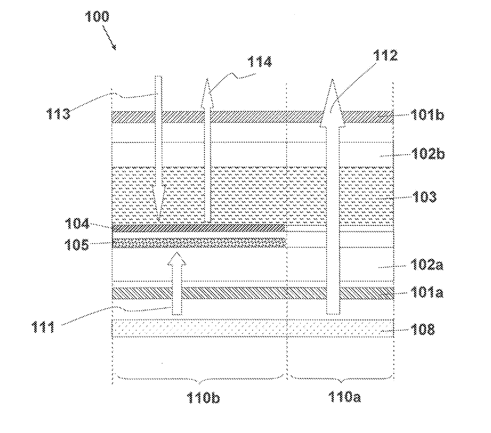
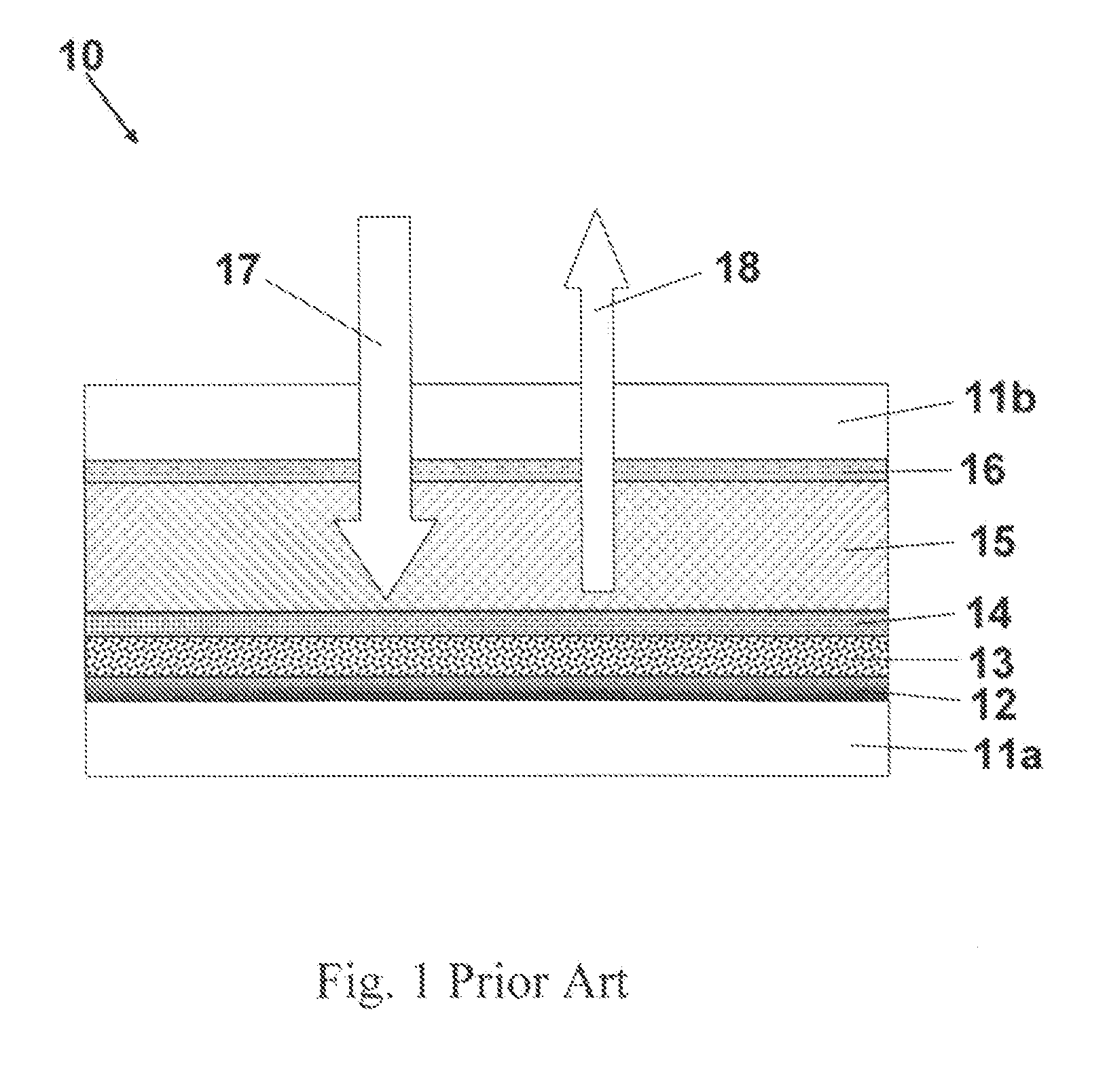
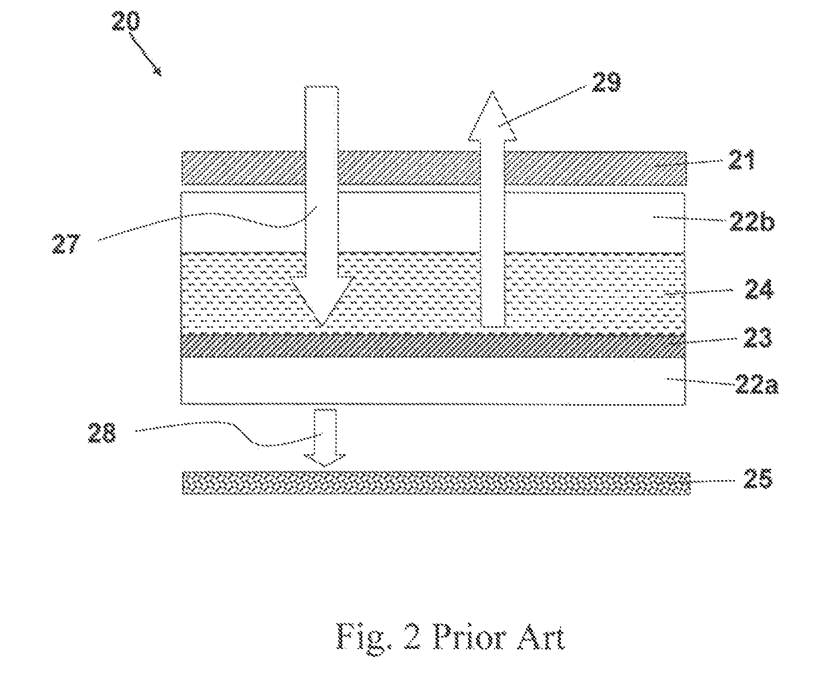
[0033]The following is a list of the reference numbers used in the drawings and the detailed specification to identify components:[0034]10 reflective LCD[0035]11a first substrate[0036]11b second substrate[0037]12 reflective electrode[0038]13 photovoltaic cell[0039]14 transparent electrode[0040]15 LC layer[0041]16 electrode[0042]17 ambient light[0043]18 left part[0044]20 reflective LCD[0045]21 top polarizer[0046]22a first substrate[0047]22b second substrate[0048]23 reflector[0049]24 LC cell[0050]25 photovoltaic cell[0051]27 ambient light[0052]28 transmitted light[0053]29 reflected light[0054]30 display pixel[0055]31a bottom linear po...


PUM

PropertyMeasurementUnit
thicknessaaaaaaaaaa
transparentaaaaaaaaaa
conductiveaaaaaaaaaa

Abstract

Methods and apparatus for a liquid crystal display with embedded photovoltaic cells for high energy efficiency. The LCD with photovoltaic cell comprises a first linear polarizer, a second linear polarizer, a first and second substrate, a liquid crystal cell formed between two substrates, and a backlight unit at the backplane of the display. Further, the display device has many repetitive pixels in the LC cell, each pixel region comprises a transmissive region that can pass the light from the backlight, and another region that is backlight blocking. A photovoltaic cell is formed on the bottom substrate to substantially cover the backlight blocking region. In one embodiment, the LCD is a transflective display, and in another embodiment, the LCD is a pure transmissive display that relies on backlight for displaying images.

Description

[0001]This application claims the benefit of priority to U.S. Provisional Application No. 61 / 258,785 filed on Nov. 6, 2009.FIELD OF THE INVENTION[0002]This invention relates to liquid crystal displays and, in particular, to methods and devices for an energy efficient liquid crystal display with embedded photovoltaic cells for each pixel.BACKGROUND AND PRIOR ART[0003]For portable display devices, low power consumption, good sun light readability, thin profile, wide viewing angle, and cost competitiveness are highly desirable. Among these requirements, low power consumption is significantly important for the device performance. For example, with low power consumption, the device can be operated for a longer time between battery charges. Previously, in order to save power consumption, a reflective typed LCD which embeds a reflector into LC cell and uses external ambient light to display images was widely employed. Besides, a reflective LCD also can have good image readability under str...

Claims


Application Information

Patent Timeline
Patent Type & Authority Applications(United States)
IPC IPC(8): G02F1/1335H01J9/00
CPCG02F2001/13324G02F1/1343
Inventor GE, ZHIBINGWU, SHIN-TSONLI, WANG-YANGWEI, CHUNG-KUANG
Owner UNIV OF CENT FLORIDA RES FOUND INC
Why Eureka
Try Eureka