
Heat removal in compact computing systems

Inactive Publication Date: 2011-05-19
APPLE INC
View PDF35 Cites 37 Cited by
  • Summary
  • Abstract
  • Description
  • Claims
  • Application Information

AI Technical Summary

Benefits of technology

[0009]In one embodiment, a compact computer heat removal system used for removing heat generated by an integrated circuit is described. In the described embodiment, the integrated circuit is mounted to a substrate that in turn is mounted to a motherboard. The heat removal system includes at least a heat pipe in thermal contact with the integrated circuit, the heat pipe is arranged to carry a heat exchanging medium that is used to transfer heat generated by the integrated circuit to an external heat sink in thermal contact with the heat pipe. The heat removal system also includes a reduced thickness integrated beam spring structure having a substantially uniform thickness used to mechanically couple the heat pipe to the motherboard. The reduced thickness of the beam structure commensurably reduces the height of the heat removal system that in turn reduces the overall integrated circuit stack height.
[0010]A compact computer heat removal system used for removing heat generated by an integrated circuit where the integrated circuit is mounted to a substrate that, in turn, is mounted to a motherboard. The compact computer heat removal system includes at least a slug in direct contact with a surface of the integrated surface. A heat pipe in thermal contact with the integrated circuit by way of the slug is used to provide support for the heat pipe and to provide a thermal conduction path between the integrated circuit and the heat pipe. In the described embodiment, the heat pipe carries a heat exchanging medium used to transfer heat generated by the integrated circuit to an external heat sink in thermal contact with the heat pipe. The compact computer heat removal system also includes a windowed stage having an opening arranged to accommodate the slug. The windowed stage is mechanically connected to the motherboard by way of fasteners. By accommodating the slug within the opening, the windowed stage reduces the thickness of the heat removal system that commensurably reduces an overall integrated circuit stack height.
[0012]In still another embodiment, a method for removing heat generated by an integrated circuit is described where the integrated circuit is mounted to a substrate, the substrate mounted to a motherboard. The method can be carried out by performing at least the following operations: providing a heat pipe in thermal contact with the integrated circuit, the heat pipe arranged to carry a heat exchanging medium that is used to transfer heat received from the integrated circuit to a heat sink, and using a reduced thickness integrated beam spring structure to mechanically couple the heat pipe to the motherboard. In the described embodiment, the reduced thickness of the beam structure reduces an overall integrated circuit stack height.

Problems solved by technology

As the density of the internal components has increased, the ability to efficiently remove the excess heat generated by those operating components having a high heat flux has been become ever more difficult and costly.
The cost of fabrication is relatively high when the heat removal system is fabricated from especially dedicated and unique components as distinguished from being fabricated from stock materials.

Method used


Image

  • Heat removal in compact computing systems
  • Heat removal in compact computing systems
  • Heat removal in compact computing systems

Examples


Embodiment Construction

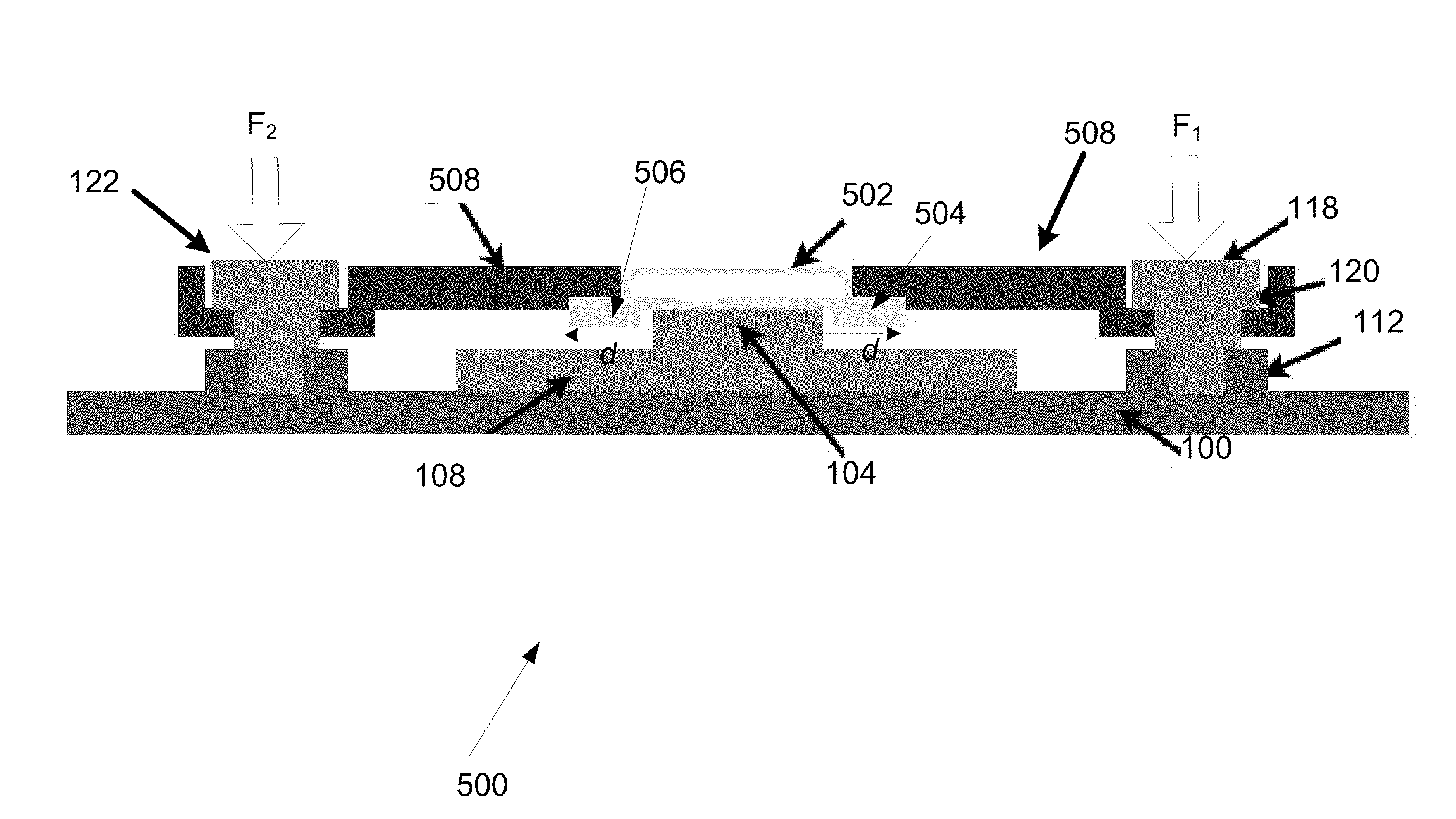
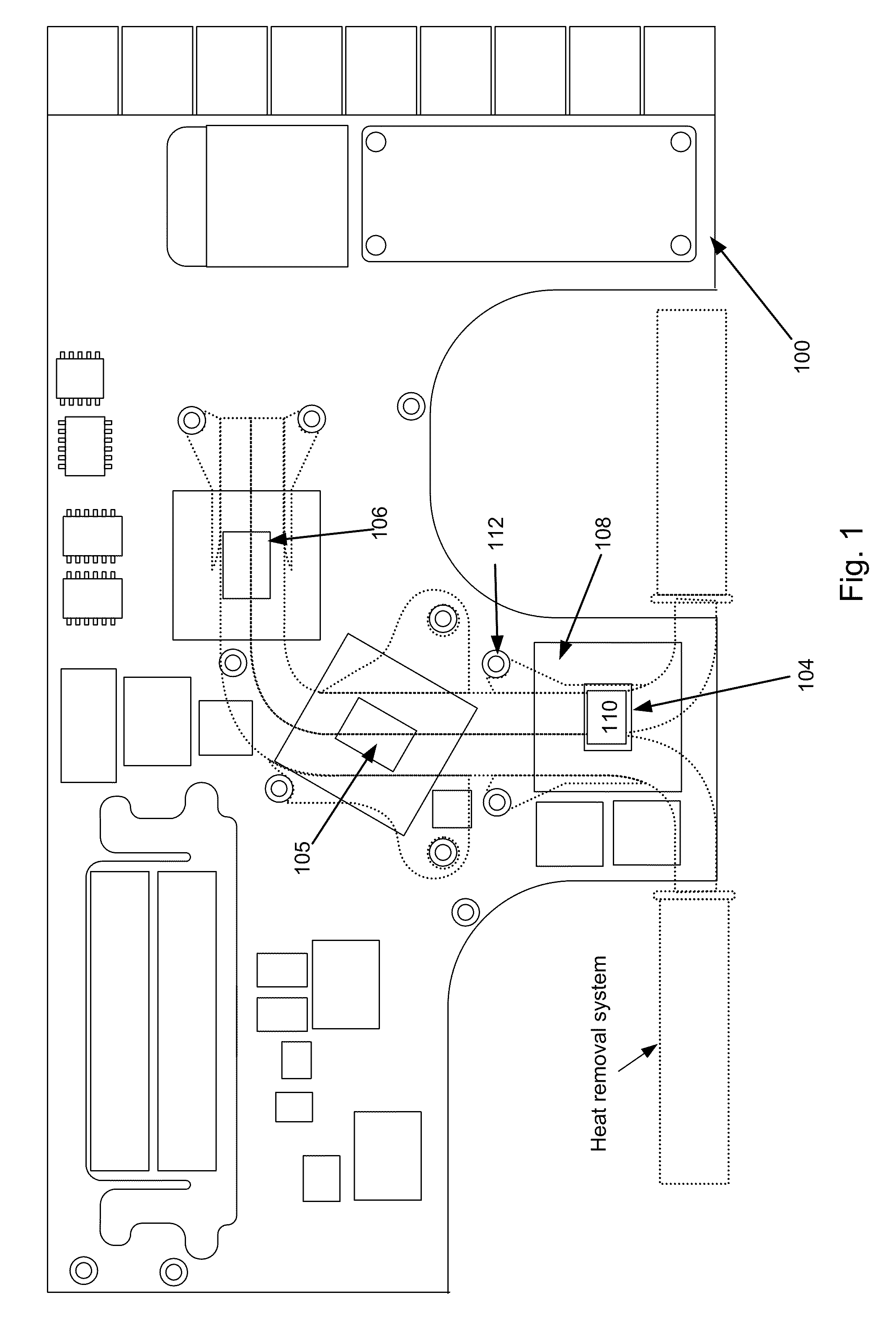
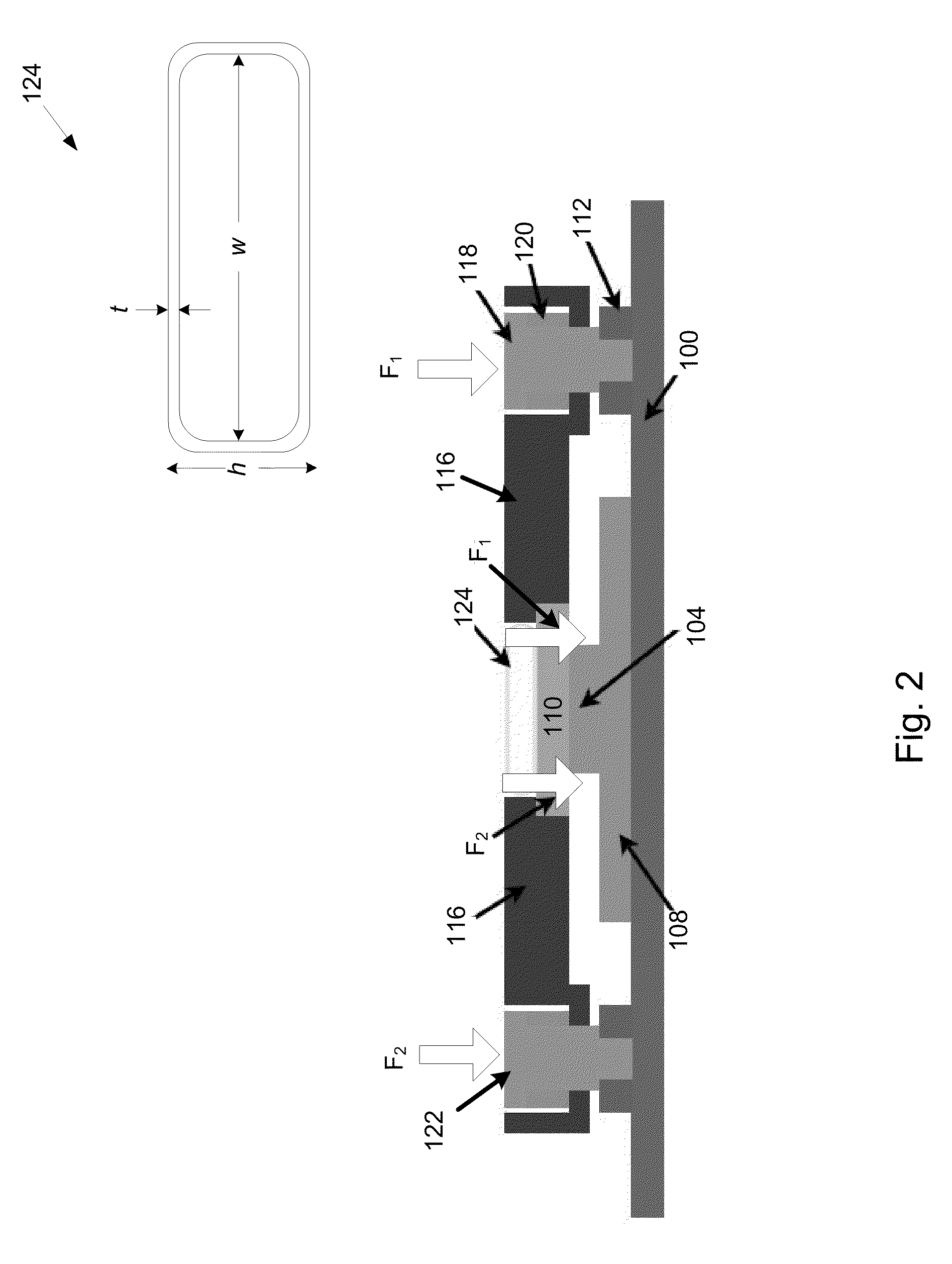
[0008]The invention relates to systems, methods, and apparatus for efficiently removing heat from components in a compact computing system such as a laptop or netbook computer.

[0009]In one embodiment, a compact computer heat removal system used for removing heat generated by an integrated circuit is described. In the described embodiment, the integrated circuit is mounted to a substrate that in turn is mounted to a motherboard. The heat removal system includes at least a heat pipe in thermal contact with the integrated circuit, the heat pipe is arranged to carry a heat exchanging medium that is used to transfer heat generated by the integrated circuit to an external heat sink in thermal contact with the heat pipe. The heat removal system also includes a reduced thickness integrated beam spring structure having a substantially uniform thickness used to mechanically couple the heat pipe to the motherboard. The reduced thickness of the beam structure commensurably reduces the height of...


PUM

PropertyMeasurementUnit
Thicknessaaaaaaaaaa
Pressureaaaaaaaaaa
Thermal resistanceaaaaaaaaaa

Abstract

A low profile heat removal system suitable for removing excess heat generated by a component operating in a compact computing environment is disclosed.

Description

BACKGROUND OF THE INVENTION[0001]1. Field of the Invention[0002]This invention relates generally to small computing devices such as laptop computers and in particular, providing a heat removal system that is efficient in both space and heat removal.[0003]2. Description of the Related Art[0004]Compact computing devices such as laptop computers, netbook computers, etc. have become ever smaller, lighter and more powerful. One factor contributing to this reduction in size can be attributed to the manufacturer's ability to fabricate various components of these devices in smaller and smaller sizes, assembling the components in ever more dense configurations, and in most cases increasing the power and or operating speed of such components. As processor power and speed has increased, however, so too has the excess heat generated. As the density of the internal components has increased, the ability to efficiently remove the excess heat generated by those operating components having a high he...

Claims


Application Information

Patent Timeline
IPC IPC(8): H01L23/40H01L23/427F28D15/04
CPCH01L23/4006H01L23/427H01L2924/3011H01L2924/0002Y10T29/49353H01L2924/00B23P15/26F28F1/00G06F1/203H05K7/2039
Inventor DEGNER, BRETT W.AUGENBERGS, PETERIS K.LIANG, FRANKHERESZTYN, AMAURY J.MATHEW, DINESHWILSON, JR., THOMAS W.
Owner APPLE INC
Features
  • Generate Ideas
  • Intellectual Property
  • Life Sciences
  • Materials
  • Tech Scout
  • Unparalleled Data Quality
  • Higher Quality Content
  • 60% Fewer Hallucinations
Learn More