Imaging device and imaging method

Inactive Publication Date: 2011-05-19
CANON KK
View PDF6 Cites 1 Cited by
  • Summary
  • Abstract
  • Description
  • Claims
  • Application Information

AI Technical Summary

Benefits of technology

[0016]Here, since the structure does not use the central portion of the lens not only when measuring the wavefront aberration, but also when obtaining the optical image of the test eye, it becomes difficult to increase field angle, and image quality is reduced due to the influence of lens aberrations. Since the reflectivity of the fundus is not uniform, in the structure in which the central portion of the lens is not used even when obtaining the optical image of the test eye, light that is incident upon and reflected by a wave-aberration sensor becomes unstable, thereby reducing the precision with which the aberrations are measured.
[0019]According to the present invention, it is possible to provide an imaging method which makes it possible to stably measure wavefront aberrations even by using an optical system that uses a central portion of a lens when obtaining an optical image of a test object in performing imaging of the optical image using adaptive optics; and to provide a device therefor.

Problems solved by technology

Here, since the structure does not use the central portion of the lens not only when measuring the wavefront aberration, but also when obtaining the optical image of the test eye, it becomes difficult to increase field angle, and image quality is reduced due to the influence of lens aberrations.
Since the reflectivity of the fundus is not uniform, in the structure in which the central portion of the lens is not used even when obtaining the optical image of the test eye, light that is incident upon and reflected by a wave-aberration sensor becomes unstable, thereby reducing the precision with which the aberrations are measured.

Method used


Image

  • Imaging device and imaging method
  • Imaging device and imaging method
  • Imaging device and imaging method

Examples


first embodiment

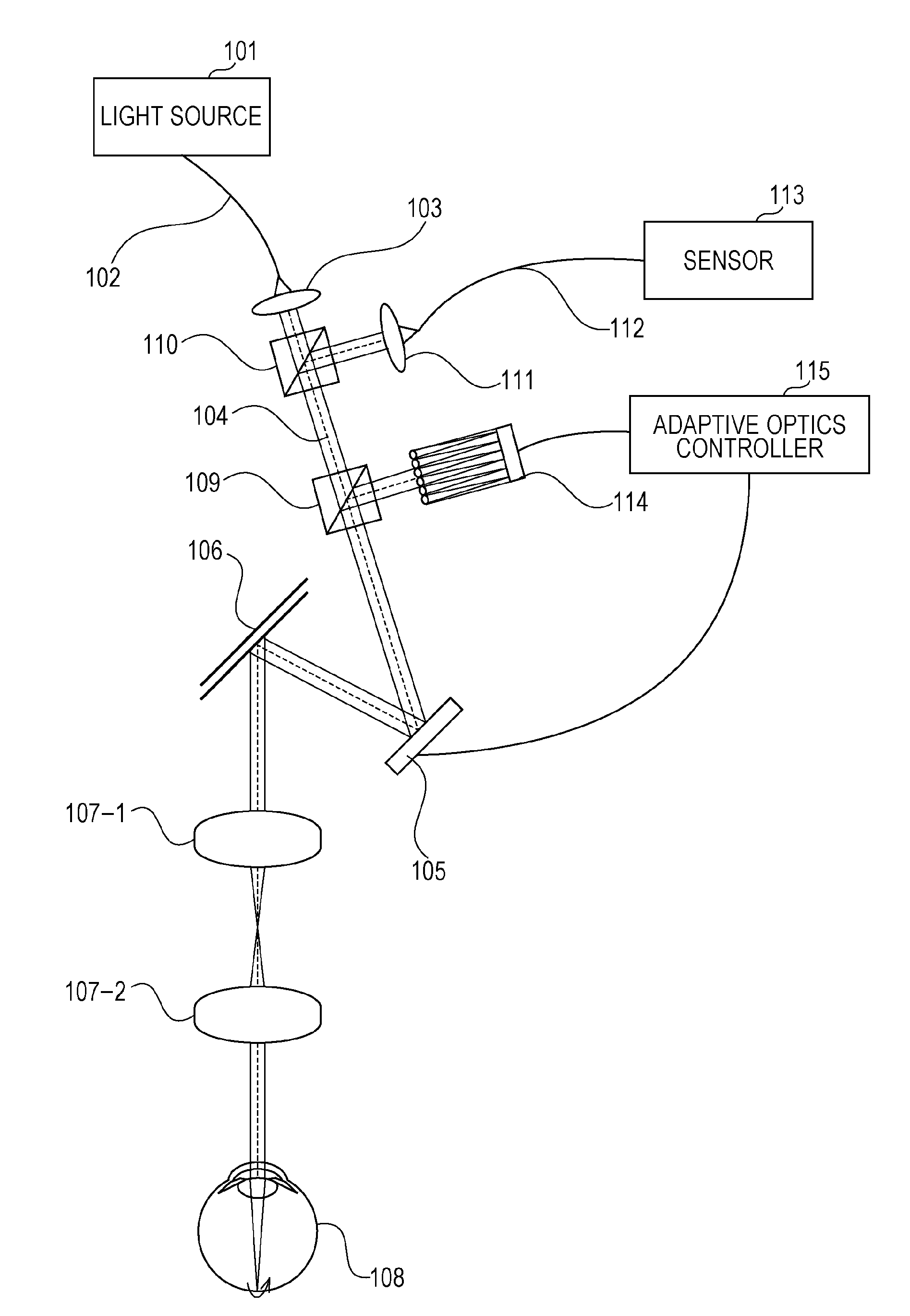
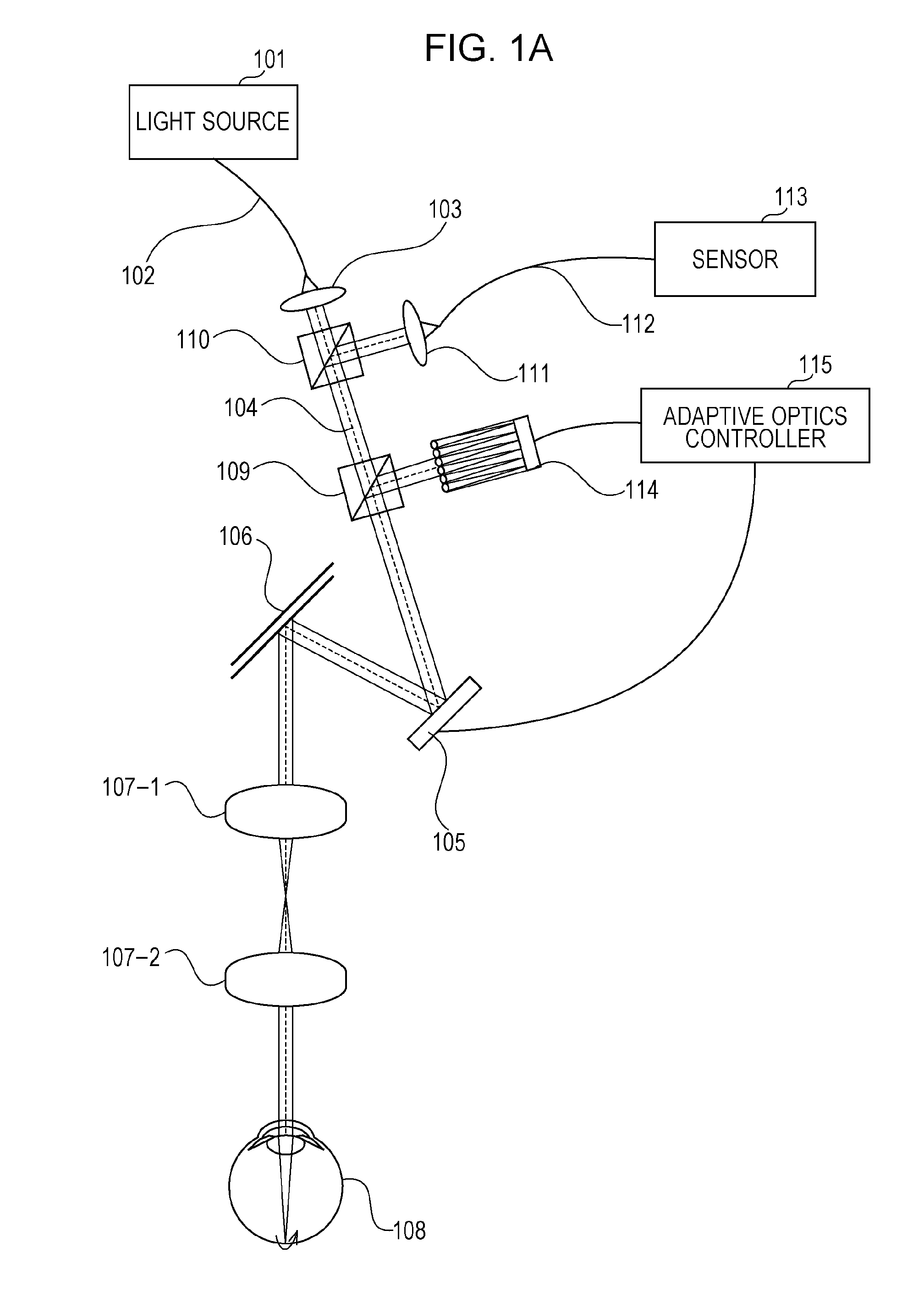
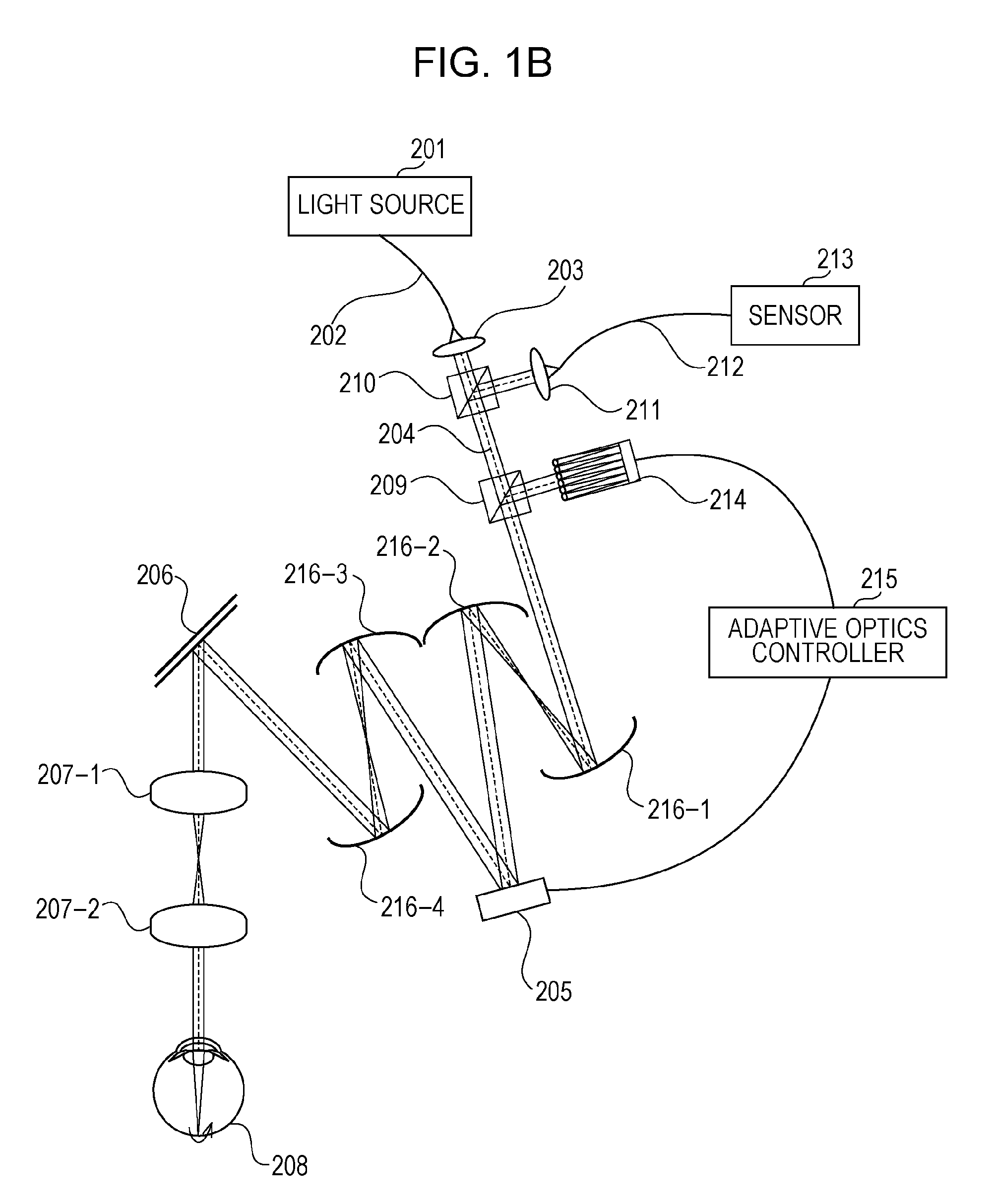
[0032]With reference to FIGS. 1A and 1B, a practical form in which an imaging method and a device therefor according to a first embodiment of the present invention are applied to a fundus photographing method (in which a test object is a test eye) and to a device therefor will be described. In the embodiment, a scanning laser ophthalmoscope (SLO) using adaptive optics is used as an example. Even in optical coherent tomography (OCT), the structure of an eyepiece portion is similar.

[0033]In FIG. 1A, reference numeral 101 denotes a light source (such as a laser, a low-coherent light source, or SLD). Although the wavelength of the light source 101 is not particularly limited, the wavelength is in the range of from 400 nm to 2 μm.

[0034]In particular, a wavelength in the range of from approximately 600 to 1500 nm is used for photographing a fundus. As a wavelength width for use in OCT, for example, a wavelength width of at least 1 nm, desirably, a wavelength width of at least 10 nm, or, m...

second embodiment

[0090]With reference to FIG. 5, a practical form in which an imaging method and a device therefor according to a second embodiment of the present invention are applied to a fundus photographing method (in which a test object is a test eye) and to a device therefor will be described. In the embodiment, an OCT device using adaptive optics is used as an example.

[0091]Light emitted from a light source 901 passes through an optical fiber 902, and is divided into signal light and reference light by an optical coupler 934.

[0092]The signal light passes through an optical fiber 935-1, is guided to a collimator 903, becomes parallel light, and is used for illumination as measurement light 904.

[0093]The measurement light 904 used for the illumination passes through a path that is similar to that in the first embodiment, and reaches an eye 908. As in the first embodiment, the light that is reflected / scattered by the eye is guided to a wavefront sensor 914 and a collimator 903.

[0094]On the basis...

example 1

[0115]As Example 1, a structural example applied to a scanning laser ophthalmoscope (SLO) will be described. The structure of the SLO in the example is basically the same as that of the SLO in the first embodiment, so that it will be described with reference to FIG. 1.

[0116]Although the example is a case applied to the scanning laser ophthalmoscope (SLO), the present invention is not limited to the SLO.

[0117]First, light emitted from a light source 101 is guided to a single-mode optical fiber 102, and light emitted from a fiber end is converted into parallel light by a collimator lens 103. The parallel light passes through a splitting optical system 110, and is used for illumination as measurement light 104. The light source is, for example, a semiconductor laser, a He—Ne laser, or an Ar laser. Its illumination power is adjusted in accordance with the wavelength.

[0118]The measurement light 104 passes through another beam splitter 109, and is reflected by a deformable mirror 105. The...


PUM


Abstract

An imaging device includes an illuminating unit configured to illuminate a measurement object with light from a light source; an aberration correcting unit configured to correct aberration of the measurement object occurring in light returning from the measurement object, the returning light being provided by light illuminating the measurement object through an area differing from a center axis of the illuminating unit; and an image obtaining unit configured to obtain an image of the measurement object on the basis of light returning from the measurement object, the returning light being provided by light that is provided after the aberration is corrected by the aberration correcting unit and that illuminates the measurement object through the center axis of the illuminating unit.

Description

BACKGROUND OF THE INVENTION[0001]1. Field of the Invention[0002]The present invention relates to an imaging method and a device therefor. More particularly, the present invention relates to an imaging method used in, for example, an ophthalmologic examination, and a device therefor.[0003]2. Description of the Related Art[0004]In recent years, for a device that obtains a tomographic image of a fundus or of the vicinity of the fundus, a scanning laser ophthalmoscope (SLO) or optical coherence tomography (OCT)(optical coherence tomographic device, or optical coherence tomographic method) is used. For the OCT, methods such as a time domain OCT (TD-OCT) (time domain method) and a spectral domain OCT (SD-OCT)(spectral domain method), are available.[0005]When the fundus is photographed by SLO or OCT, the fundus needs to be photographed through an optical structure of an eye, such as a cornea and an eye lens.[0006]An increase in resolution causes aberration of the cornea or the eye lens to ...

Claims


Application Information

Patent Timeline
IPC IPC(8): A61B3/14G01B11/24
CPCG01N21/4795G01N2021/1787A61B3/14G02B26/0825G02B26/06
Inventor NOZATO, KOJI
Owner CANON KK
Why Eureka
Try Eureka