Image receiver elements

a receiver element and image technology, applied in the field of image receiver elements, can solve the problems of limiting the type of materials that can be incorporated into the layer, affecting the quality of the image, so as to improve the humidity sensitivity, improve the color density, and improve the effect of dye transfer efficiency

Active Publication Date: 2011-05-19
KODAK ALARIS INC
View PDF11 Cites 27 Cited by
  • Summary
  • Abstract
  • Description
  • Claims
  • Application Information

AI Technical Summary

Benefits of technology

[0019]The thermal, non-silver halide-containing image receiver elements of this invention exhibit several important advantages, not all of which may be found in every embodiment. The image receiving layer can be coated out of aqueous formulations thereby avoiding organic solvent coating. The elements of this invention can have a number of other advantages including high dye transfer efficiency that leads to a more saturated color density, much improved humidity sensitivity (or less sensitive to humidity), less image bleeding, and reduced front-to-back blocking (or adhesion) for image-receiving layer coatings with aqueous formulations.

Problems solved by technology

Such methods involve expensive, polluting, and hazardous manufacturing processes.
Such methods restrict the type of materials that can be incorporated into the layer due to the high temperatures required for the extrusion process.
Although such aqueous coating methods reduce or eliminate the use of hazardous solvents, and high temperature coating processes, such aqueous-coated layers cause problems in typical customer printing environments where high speed printing requires a smooth separation of donor ribbon element and receiver element with no sticking between the two surfaces.
Printing in high humidity environments can be particularly troublesome for sticking with typical aqueous-coated receivers.
Moreover, such receiver elements are often deficient in providing adequate dye density.
Furthermore, imaged prints bearing the aqueous coated layer are not robust in situations where the print is contacted with water and separation of the layer can occur.
Thus, a common problem with the use of some thermal dye donor elements and corresponding thermal dye receiver elements is that at high dye transfer temperatures, the polymers in the elements can soften and cause adherence between the elements, resulting in sticking and tearing of the elements during separation.
Areas within the donor element (other than the transferred dyes) can adhere to the receiver element, rendering the receiving element useless.
Such copolymers are difficult to synthesize and are rarely commercially available.
The technology as described in this patent does not provide adequate maximum densities.

Method used


Image

  • Image receiver elements
  • Image receiver elements
  • Image receiver elements

Examples


examples

[0085]The polyurethane latexes used in the practice of this invention were prepared as dispersions using the following procedure:

[0086]In a 1-liter, three-necked round bottom flask equipped with a stirrer, water condenser, and nitrogen inlet were placed 35.4 g (0.0177 moles) of polycarbonate polyol (average Mn=2000) (Aldrich Chemical), 4.56 g (0.034 moles) of 2,2-bis(hydroxymethyl)propionic acid (DMPA), 17.87 g (0.1983 mole) of 1,4-butanediol, 52 g of tetrahydrofuran (THF), and 0.50 ml of dibutyltin dilaurate (catalyst). The reaction temperature was adjusted to 65° C. When a homogenous solution was obtained, 55.57 g (0.25 moles) of isophorone diisocyanate (IPDI) was slowly added followed by 10 g of THF. The reaction temperature was raised to 75° C. and maintained for 24 hours to complete the reaction, resulting in an intermediate containing no residual free isocyanate. The free isocyanate content was monitored by the disappearance of the NCO absorption peak by infrared spectroscopy....


PUM

PropertyMeasurementUnit
Tgaaaaaaaaaa
thicknessaaaaaaaaaa
thicknessaaaaaaaaaa

Abstract

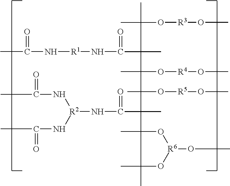
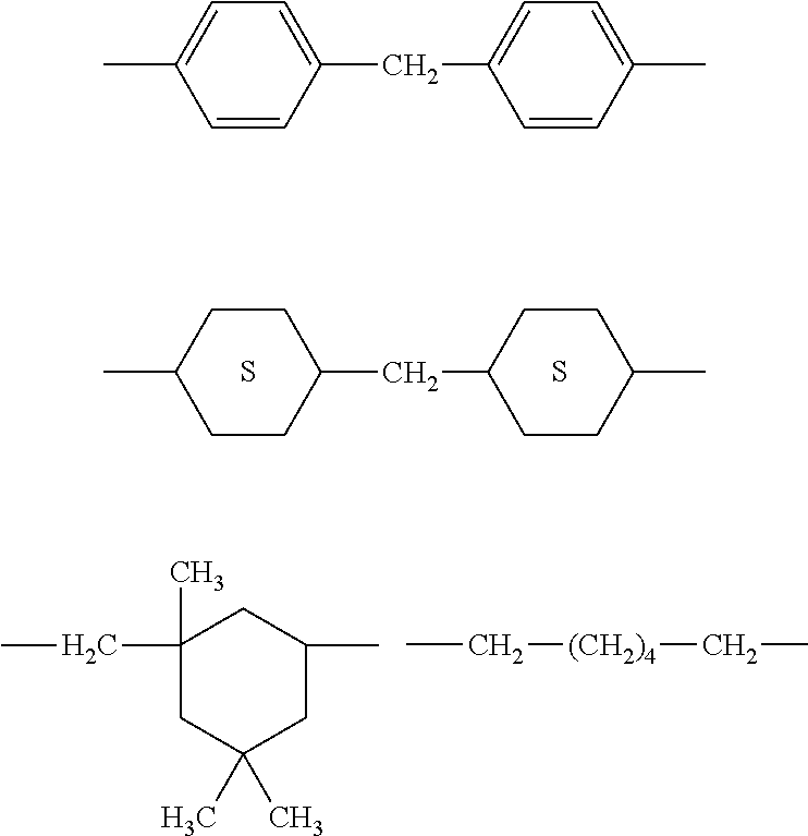
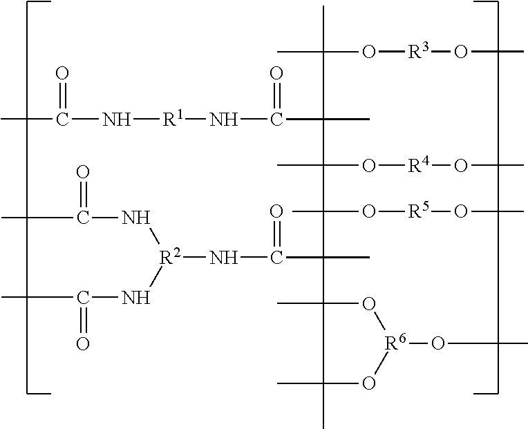
An image receiver element includes a water-soluble or water-dispersible polyurethane binder in the image receiving layer. This polyurethane has a Tg of from about 60 to about 80° C., a molecular weight of at least 25,000, and an acid number of from about 16 to about 35 mg KOH/g. Moreover, the polyurethane comprises from about 42 to about 60 weight % of recurring urethane units, from about 8 to about 20 weight % of alkylene glycol recurring units, from about 18 to about 40 weight % of carbonate recurring units having aliphatic side chains, and from about 3 to about 15 weight % of recurring units having a water-soluble or water-dispersible acid group, based on total binder weight.

Description

FIELD OF THE INVENTION[0001]This present invention relates to image receiver elements that have at least one aqueous-coated image receiving layer containing a specific water-dispersible polyurethane (latex) binder. Such image receiving elements can be used as thermal dye transfer receiver elements that can be used in a thermal assembly in combination with a dye image donor element.BACKGROUND OF THE INVENTION[0002]In recent years, thermal transfer systems have been developed to obtain prints from pictures that have been generated from a camera or scanning device. According to one way of obtaining such prints, an electronic picture is first subjected to color separation by color filters. The respective color-separated images are then converted into electrical signals. These signals are then transmitted to a thermal printer. To obtain the print, a cyan, magenta or yellow dye-donor element is placed face-to-face with a dye receiver element in an image assembly. The two are then inserted...

Claims


Application Information

Patent Timeline
Patent Type & Authority Applications(United States)
IPC IPC(8): B41M5/40C08G18/00C08L75/04
CPCB41M5/5281C08G18/0823C08G18/3206C08G18/755C08G18/664C08G18/6659C08G18/44
Inventor KUNG, TEH-MINGFALKNER, CATHERINE A.WANG, YONGCAIMAJUMDAR, DEBASIS
Owner KODAK ALARIS INC
Why Eureka
Try Eureka