
Light-emitting element

Active Publication Date: 2011-05-26
TORAY IND INC
View PDF4 Cites 34 Cited by
  • Summary
  • Abstract
  • Description
  • Claims
  • Application Information

AI Technical Summary

Benefits of technology

[0021]The present invention makes it possible to provide an organic electric field light emitting device that achieves both of the low-voltage driving operation and high luminance efficiency.

Problems solved by technology

Among these, in the case when the luminance efficiency is poor, an image output required for high luminance is not available to cause high power consumption in outputting an image with desired luminance.

Method used


Image

  • Light-emitting element
  • Light-emitting element
  • Light-emitting element

Examples


example 1

[0099]A glass substrate (sputtered product at 11 Ω / sq, made by Geomatic Company) on which an ITO transparent conductive film was deposited with a thickness of 150 nm was cut into plates of 38×46 mm, and each of these was etched. After the resultant substrate had been ultrasonic washed for 15 minutes by using “SEMICO CLEAN 56” (trade name, made by Furuuchi Chemical Corporation), it was washed with ultrapure water. Immediately before forming the resultant substrate into a device, it was subjected to a UV-ozone treatment for one hour, and placed inside a vacuum vapor deposition device so that the inside of the device was evacuated up to 5×10⁻⁴ Pa or less in vacuum degree. First, copper phthalocyanine was formed thereon with a thickness of 10 nm as a hole injection material by using a resistance heating method, and 4,4′-bis(N-(1-naphthyl)-N-phenylamino)biphenyl was vapor deposited thereon with a thickness of 50 nm as a hole transporting material. Next, as emissive materials, a compound ...

examples 2 to 32

[0101]The same processes as those of example 1 were carried out except that materials shown in Tables 1 and 2 were used as the host material, dopant material and electron transporting layer; thus, a light emitting device was produced. The results of the respective examples are shown in Tables 1 and 2.

example 33

[0104]A glass substrate (sputtered product at 11 Ω / sq, made by Geomatic Company) on which an ITO transparent conductive film was deposited with a thickness of 165 nm was cut into plates of 38×46 mm, and each of these was etched. After the resultant substrate had been ultrasonic washed for 15 minutes by using “SEMICO CLEAN 56” (trade name, made by Furuuchi Chemical Corporation), it was washed with ultrapure water. Immediately before forming the resultant substrate into a device, it was subjected to a UV-ozone treatment for one hour, and placed inside a vacuum vapor deposition device so that the inside of the device was evacuated up to 5×10⁻⁴ Pa or less in vacuum degree. First, 1,4,5,8,9,12-hexa-aza-triphenylene hexacarbonitrile was formed thereon with a thickness of 10 nm as a hole injection material by using a resistance heating method, and 4,4′-bis(N-(1-naphthyl)-N-phenylamino)biphenyl was vapor deposited thereon with a thickness of 50 nm as a hole transporting material. Next, as e...


PUM


Abstract

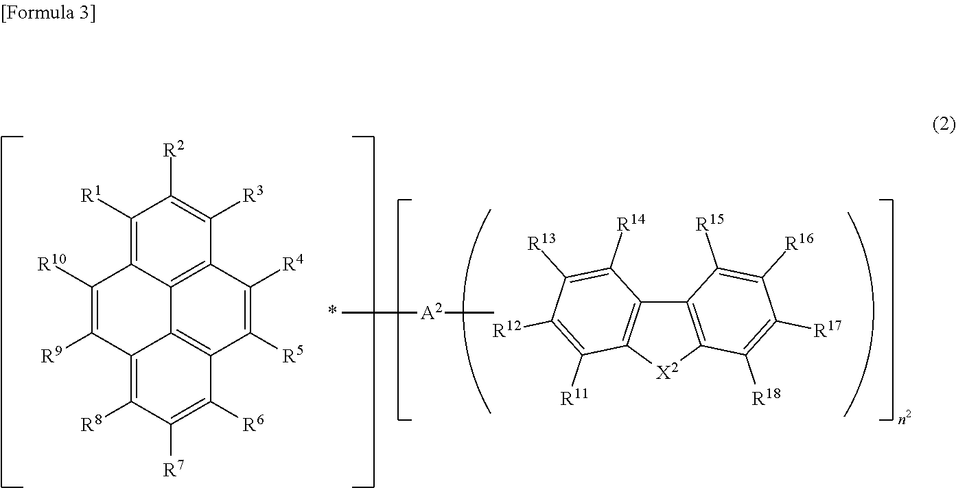
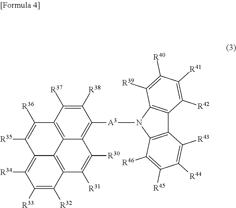
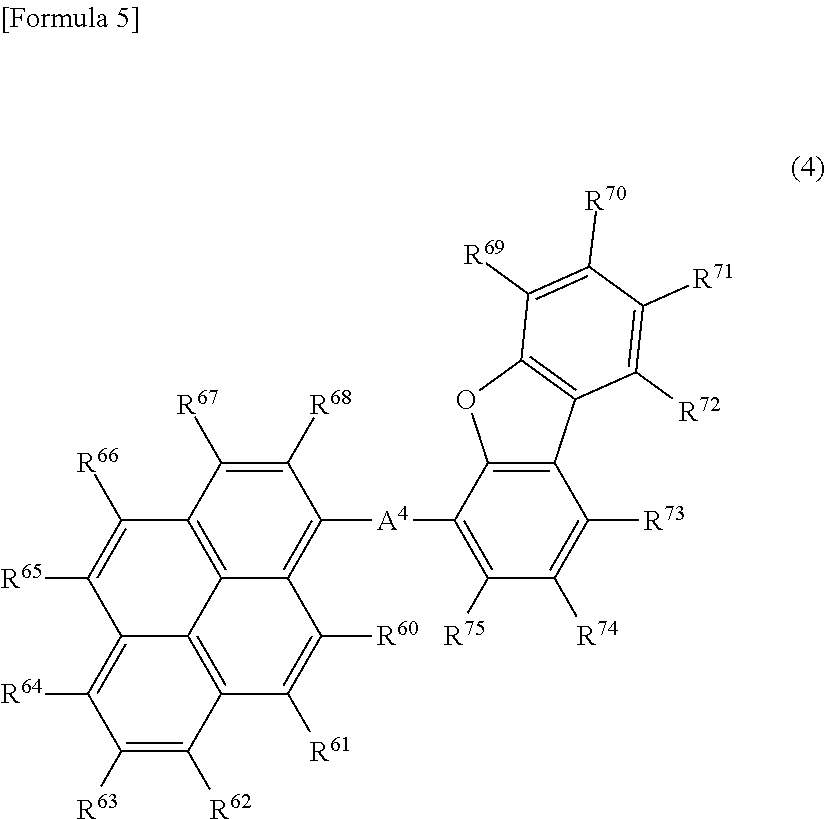
The present invention relates to an organic thin-film light emitting device containing an organic compound represented by formula (1) and a donor compound. the light emitting device ca achieve both of the low-voltage driving operation and high luminance efficiency.YA1-Ar)n<sup2>1< / sup2>  (1)(Y represents either substituted or unsubstituted pyrene, or substituted or unsubstituted anthracene. A1 is selected from the group consisting of a single bond, an arylene group, and a hetero arylene group. Ar is selected from the group consisting of a carbazolyl group, a dibenzofuranyl group, and a dibenzothiophenyl group. These groups may be substituted or unsubstituted, and n1 is an integer of 1 to 3.)

Description

TECHNICAL FIELD[0001]The invention relates to a pyrene compound or an anthracene compound effectively used for a charge transporting material, and a light emitting device that uses these, and more particularly concerns a light emitting device that is applicable to various fields, such as display devices, flat panel displays, backlights, lighting fittings, interior goods, signs, signboards, electronic cameras, and light signal generators.BACKGROUND ART[0002]In recent years, studies have been vigorously made on an organic thin-film light emitting device that emits light when electrons injected from a cathode and holes injected from an anode are recombined inside an organic fluorescent body sandwiched between the two electrodes. This light emitting device is characterized by a thin structure, high luminance light emission under a low driving voltage, and light emissions with multiple colors achieved by selecting fluorescent materials, and has drawn public attentions.[0003]These studies...

Claims


Application Information

Patent Timeline
IPC IPC(8): H01L51/54
CPCC09B57/00C09B57/001C09B57/10C09B1/00H10K85/622H10K85/654H10K85/6574H10K85/6572H10K50/14H10K50/17
Inventor NAGAO, KAZUMASAARAI, TAKESHIIKEDA, TAKESHITOMINAGA, TSUYOSHITANAKA, DAISAKUICHIHASHI, YASUNORIUEOKA, KOJI
Owner TORAY IND INC
Learn More