Thermally assisted magnetic head-slider and head-gimbal assembly

a head-gimbal and magnetic head technology, applied in the field of magnetic head-slider and head-gimbal assembly, can solve the problems of thermal instability of grains, limit the size of magnetic heads, and difficulty in increasing anisotropy field, so as to prevent the generation of contamination and suppress the increase of coupling loss

Active Publication Date: 2011-05-26
HITACHI LTD
View PDF6 Cites 35 Cited by
  • Summary
  • Abstract
  • Description
  • Claims
  • Application Information

AI Technical Summary

Benefits of technology

[0023]According to the embodiments of the present invention, it is possible to suppress an increase in coupling loss due to heat produced by a semiconductor laser unit and to prevent generation of contamination in a thermally assisted magnetic head-slider and a head-gimbal assembly.

Problems solved by technology

In the magnetic recording media, reducing the grain size causes noise reduction; however, a problem in which the grains become thermally unstable occurs.
However, since there is a limit to the size of a magnetic head for recording, it becomes difficult to increase the anisotropy field, that is, to enhance the coercivity.
As a result, high density recording becomes impossible.
However, since use of the above-mentioned optical component increases optical loss (hereinafter, referred to as coupling loss) in a coupling part, it is necessary to guide the light with as few components as possible.
As a result, there is a problem in which coupling loss occurs.
An increase in the coupling loss results in an increase in consumed power, which is a big problem.
This contamination is a material that inhibits flying in a magnetic disk device, and once contamination is generated, at the worst case scenario, probability in that a head crash occurs is high.
As a result, there is a problem in which the reliability of the magnetic disk device is undermined.

Method used


Image

  • Thermally assisted magnetic head-slider and head-gimbal assembly
  • Thermally assisted magnetic head-slider and head-gimbal assembly
  • Thermally assisted magnetic head-slider and head-gimbal assembly

Examples


embodiment 1

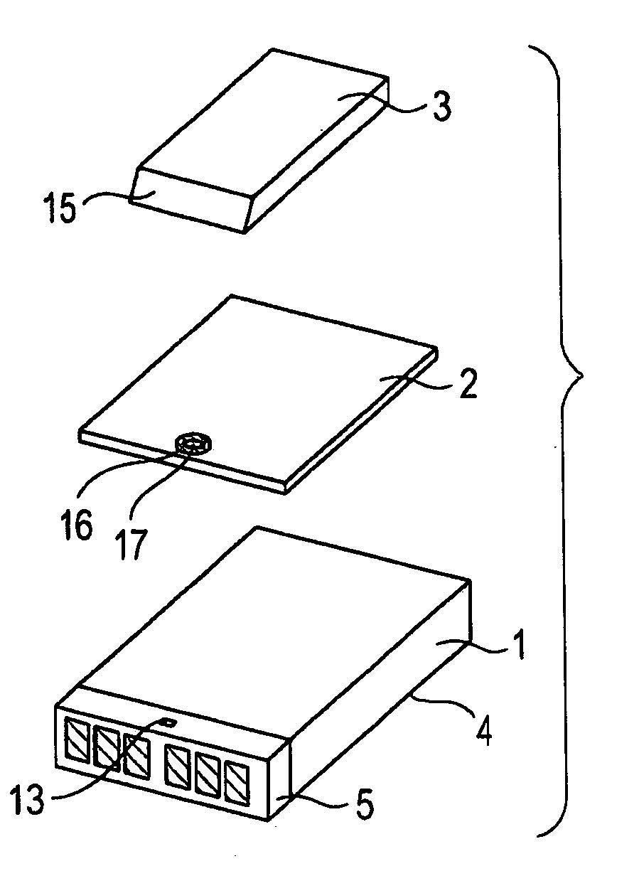
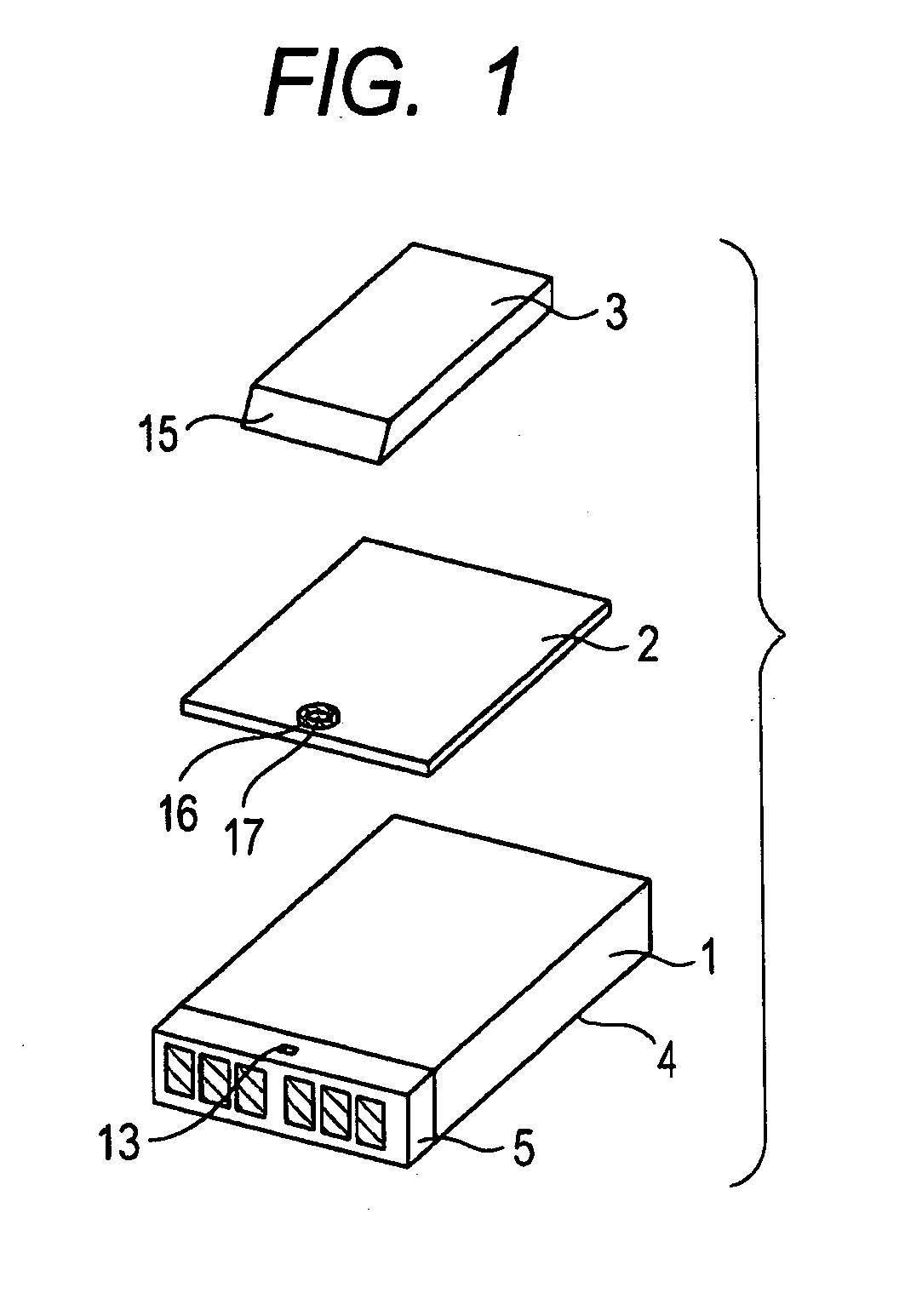
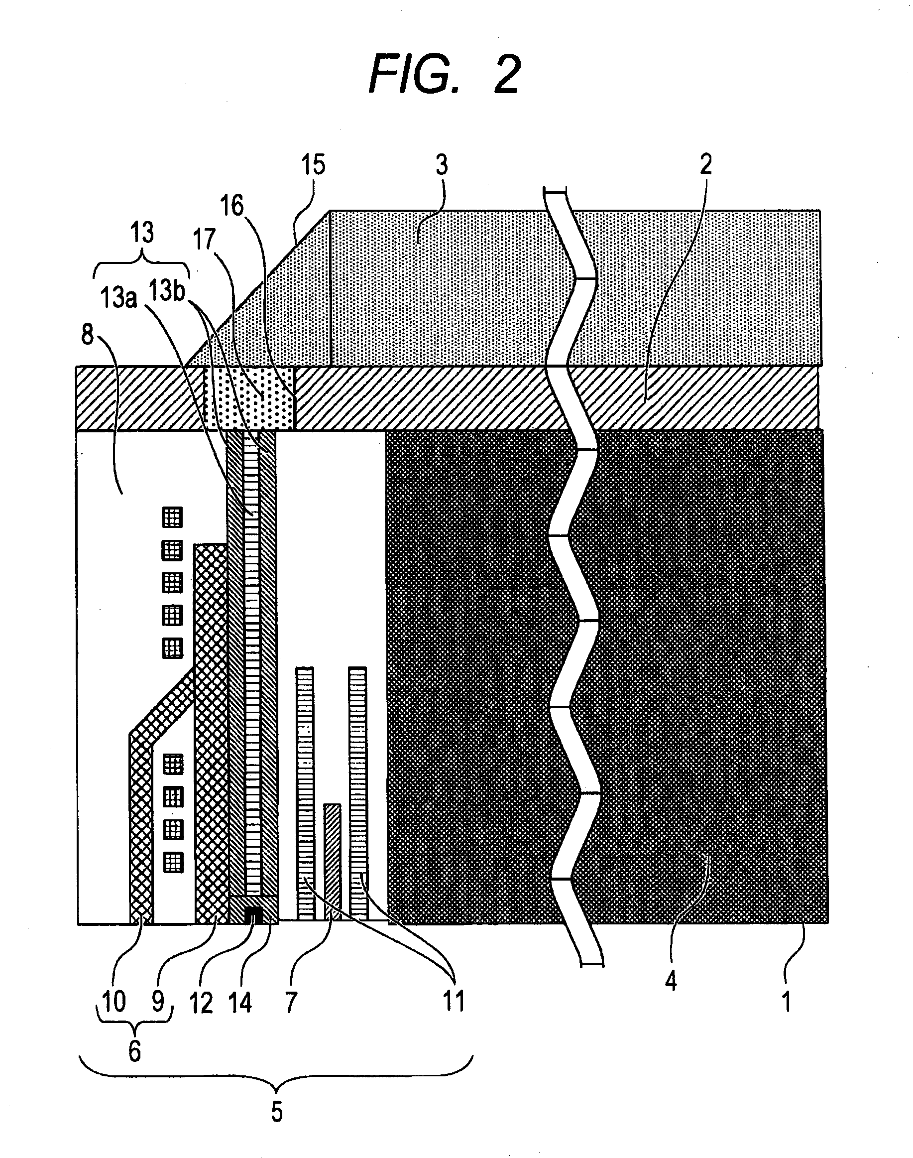
[0032]FIG. 1 is an assembled perspective view of a thermally assisted magnetic head-slider according to Embodiment 1 of the present invention. FIG. 2 shows a cross-sectional view of the thermally assisted magnetic head-slider according to Embodiment 1 of the present invention. The thermally assisted magnetic head-slider according to Embodiment 1 is composed of an air-bearing slider 1 flying on magnetic recording medium, a metal film 2, and a semiconductor laser unit 3 that are stacked with, for example, an adhesive interposed therebetween. The air-bearing slider 1 is composed of a slider substrate 4, and a thin film magnetic head unit 5 including a recording / reproducing element, an optical waveguide, and a near-field light element. The slider substrate 4 is made of a material represented by a sintered body of TiC and Al2O3. At an air-bearing surface for flying on magnetic recording medium, a fine step (a step bearing) is provided by a process such as ion milling or etching, and face...

embodiment 2

[0041]Embodiment 2 of the present invention will be described with reference to FIGS. 6 and 7. Components having the same functions as those of Embodiment 1 are designated by the same reference numerals and a description thereof is omitted. In Embodiment 2, an embodiment when the distance between the light emitting opening of the semiconductor laser unit 3 and the light receiving opening of the optical waveguide 13 (hereinafter, referred to as an optical length) is short is disclosed. It is known that as an optical length decreases, coupling loss decreases. In Embodiment 2, the optical length is 20 μm. In this embodiment, a configuration having a short optical length is provided by eliminating a Si substrate by etching.

[0042]FIG. 6 shows an assembled view of Embodiment 2, and FIG. 7 shows a cross-sectional view of a thermally assisted magnetic head-slider according to Embodiment 2 of the present invention. A Si substrate 20 is used as a substrate, and has a thickness of 100 μm. The ...


PUM

PropertyMeasurementUnit
widthaaaaaaaaaa
lengthaaaaaaaaaa
angleaaaaaaaaaa

Abstract

A thermally assisted magnetic head-slider includes an air-bearing slider, a metal film, and a semiconductor laser unit. The metal film having an aperture in a part through which light from the semiconductor laser unit passes is disposed between a surface opposite to an air-bearing surface of the air-bearing slider and the semiconductor laser unit, and a material to adjust refractive index is provided in the aperture. A bottom surface of the metal film including the material to adjust refractive index is disposed to be in close contact with a surface opposite to the air-bearing surface side of the air-bearing slider, and the semiconductor laser unit is disposed to be in close contact with a top surface of the metal film including the material to adjust refractive index.

Description

[0001]The present application claims priority from Japanese application serial No. 2009-267549, filed on (Nov. 25, 2009), the content of which is hereby incorporated by reference into this application.FIELD OF THE INVENTION[0002]The present invention relates to a magnetic head-slider and a head-gimbal assembly for realizing a high density recording of a magnetic disk device, and more particularly, to a magnetic head-slider and a head-gimbal assembly for thermally assisted recording.BACKGROUND OF THE INVENTION[0003]With the rapid improvement in performance of a computer system such as a mobile PC, a workstation, or a high-capacity server, high density recording of a magnetic disk device which is an external recoding device for such a computer system is being required. In order for high density recording of a magnetic disk device, it is necessary to reduce a distance between magnetic recording medium and a magnetic head-slider, reduce the size of grains constituting a magnetic film of...

Claims


Application Information

Patent Timeline
Patent Type & Authority Applications(United States)
IPC IPC(8): G11B11/00
CPCG11B5/1278G11B5/314G11B2005/0021G11B2005/0005G11B5/6088
Inventor KATO, YUKIONANIWA, IRIZO
Owner HITACHI LTD
Why Eureka
Try Eureka