
Phase difference in a mobile communication network

a mobile communication network and phase difference technology, applied in the field of transmission systems, can solve the problems of hsdpa users with equaliser receivers being severely affected, suited for an optimum equalisation process, and affecting the performance of legacy users, so as to avoid service interruption

Inactive Publication Date: 2011-05-26
VONDAFONE GROUP
View PDF2 Cites 19 Cited by
  • Summary
  • Abstract
  • Description
  • Claims
  • Application Information

AI Technical Summary

Benefits of technology

[0019]As a result, a mechanism is provided for deriving the phase difference introduced by the transmit branches for multiple antenna transmit systems. This facilitates, for example, the optimization of the system based on an automatic calibration of the phase offset introduced by the multiple transmit branches. Multiple antenna transmission techniques such as MIMO may thus be optimized without impacting legacy users, bearing in mind that the phase offsets could vary on a cell or sector basis. The detection of the phase difference may be performed after or before the RF cables (connecting the final network element of the system to the antenna). The detection may even be performed within the antenna. However, it preferably is performed after the power amplifiers and filters of the transmission branches.
[0023]If the first transmission branch and the second transmission branch are configured to operate on a first carrier frequency and the transmission system is configured to additionally operate on a second carrier frequency, preferably during the phase calibration mode all traffic data is transmitted and received on the first carrier frequency. In this way service interruption is avoided. Similarly, the calibration requiring switch-off of traffic on the second carrier can be done while the first frequency carrier is in operation.

Problems solved by technology

However in practice this feature has been found to affect the performance of legacy users.
In particular HSDPA users with equaliser receivers can be severely impacted.
This is due to the time transformation which is performed by STTD, which is not suited for an optimum equalisation process.
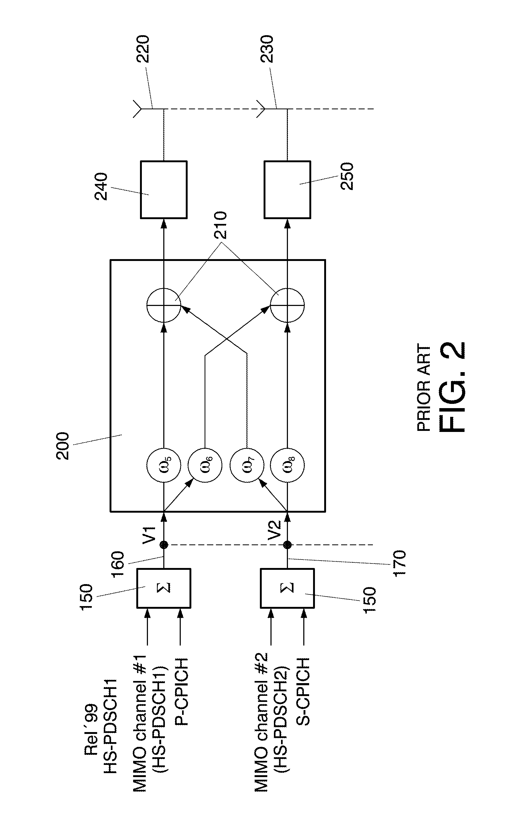
Whilst this fixed phase offset between the two transmit ports can improve performance of legacy HSPA users (e.g. 90° phase offset as explained in co-pending Spanish Patent application 200930517, the contents of which are incorporated herein by reference), other phase shifts could actually worsen performance of legacy users.
The accuracy in terms of phase is an issue in the Radio Frequency (RF) elements of the transmit branches, such as the power amplifier and the duplex filters.
If the calibration were to be performed using the radio signals according to the mobile network standard, e.g. 3G signals, the phase difference detection means would be complex and costly (in case of 3G a complete 3G receiver would be needed to detect the phase of the signals and thereby the phase difference between them).

Method used


Image

  • Phase difference in a mobile communication network
  • Phase difference in a mobile communication network
  • Phase difference in a mobile communication network

Examples


first embodiment

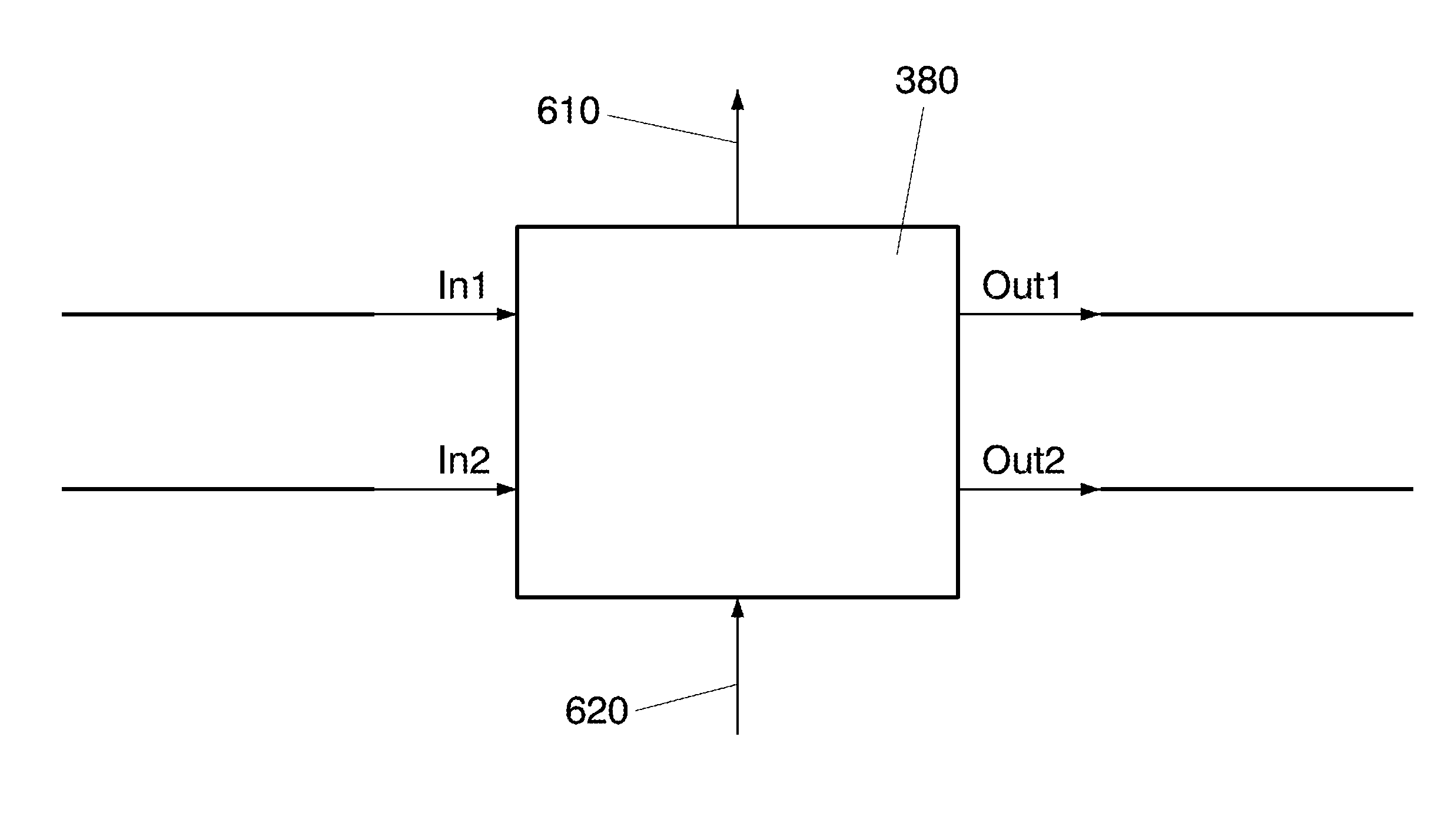
[0040] as shown in FIG. 3, the calibration is performed at Node B (base station) 300. A calibration signal generator 310 generates a calibration signal 320, which is fed to the inputs of a first RF transmission branch 330 up to the first antenna port 340 of the antenna arrangement 350 (which consists of two physical antennas each one radiating one of the radio signals) and a second RF transmission branch 360 up to the second antenna port 370 of the antenna arrangement 350. Apart from the power amplifier 240,250 each of the transmission branches 330,360 comprises other RF components, such as duplex filters (not shown) and RF cables. The components of the RF transmission branches are not designed to have the same phase or a controlled phase difference.

[0041]A Phase Detection Module (PDM) 380 measures the phase difference between the two transmission branches thanks to a calibration signal of the first and second transmission branch at the input of the antenna connector cables between ...

second embodiment

[0042] as shown in FIG. 4 the calibration signal 320 is applied to the input of the transmission branches in the Base Band Unit (BBU) 410 in the distributed Node B concept and the phase detection module 380 is implemented in the Remote Radio Unit (RRU) 420.

[0043]This type of solution allows controlling the phase up to the antenna connectors of the Node B (or RRU). To achieve the desired polarization radiated at the antenna this requires making sure any phase shift introduced in the transmission branches after the Node B is known and controlled. One possibility is to use for the connectors from Node B to antenna the same RF cable length to make sure that the phase difference at the inputs of the antenna arrangement 350 remains unchanged with respect to the phase difference at the input of the antenna connectors. The VAM entity can then compensate the phase difference in its weighting in order to achieve the desired polarization of the signals once radiated over the air. This would be...

third embodiment

[0045] in order to have full control of the phase of the signals at the input ports of the antenna arrangement 350, the phase difference detection is performed by means of a phase detection module (PDM) integrated to the antenna or an external module directly connected to the antenna ports 340,370, as shown in FIG. 5. The PDM 380 signals the measured phase offset back to the Node B as an input to the VAM entity 200, similarly to well known Remote Electrical Tilt systems. The signalling message may be sent using the Iuant interface according to the 3GPP Iuant standard—adapted from the specifications from the Antenna Interface Standards Group (AISG)—defined in 3GPP TS25.460 UTRAN Iuant Interface General Aspects and Principles Release 6, 3GPP TS25.461 UTRAN Iuant Interface Layer 1, Release 6, 3GPP TS25.462 UTRAN Iuant Interface Signalling Transport, Release 6 and 3GPP TS25.463 UTRAN Iuant Interface Remote Electrical Tilting (RET) (each of which are incorporated herein by reference in t...


PUM


Abstract

A system and method are described for detecting and controlling the phase difference introduced to radio signals by transmission branches of a transmission system in a mobile communication network. Periodically a calibration signal is generated at an input of the transmission branches during a phase calibration mode. The phase difference introduced by the two transmission branches is detected by detecting the phase difference between the calibration signal, which has at least partly passed through the first transmission branch and the calibration signal, which has at least partly passed through the second transmission branch. The phase difference between the radio signals is controlled based on the detected phase difference.

Description

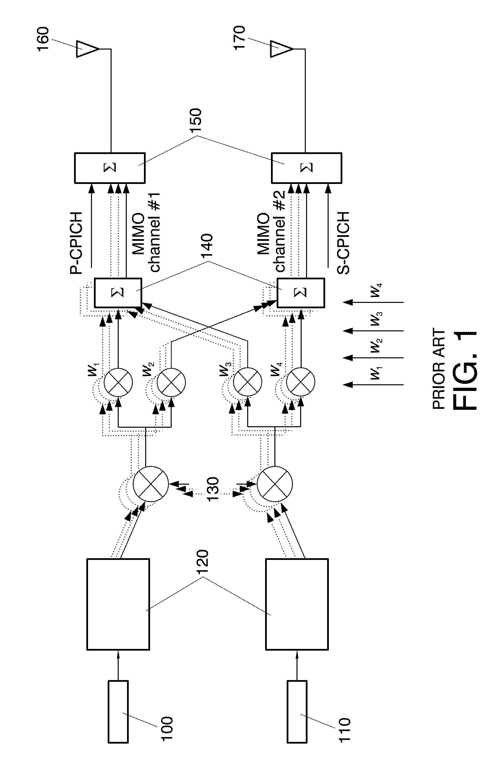
TECHNICAL FIELD[0001]Embodiments of the present invention relate to transmission systems for use in a mobile communication network and more specifically to the detection and control of the phase difference introduced by transmission branches of such a transmission system.DESCRIPTION OF RELATED ART[0002]HSDPA (High Speed Downlink Packet Access) is a packet-based data service in 3rd generation (3G) W-CDMA (Wideband Code Division Multiple Access) systems, which provides high-speed data transmission (with different download rates e.g. 7.2 / 10.8 / 16.2 / 21.6 / 28.8 Mbps over a 5 MHz bandwidth) to support multimedia services.[0003]In order to reach the highest peak rates (28.8 Mbps with 3GPP Release), the MIMO (Multiple Input Multiple Output) feature is used in HSDPA, in which multiple antennas are implemented at both base station (Node B) and mobile terminals (UE: User Equipment).[0004]The basic MIMO feature as standardised in 3GPP Release 7 is based on two transmitter antennas (at the node B)...

Claims


Application Information

Patent Timeline
Patent Type & Authority Applications(United States)
IPC IPC(8): H04L1/02
CPCH01Q3/267H04B17/12H04B17/0085H04B7/0682H04B7/06
Inventor DE PASQUALE, ANDREAEXADAKTYLOS, KYRIAKOSALCAZAR VIGUERA, ESPERANZADIAZ MATEOS, MARIAGARRIGA MUNIZ, BEATRIZDOMINGUEZ ROMERO, FRANCISCO JAVIERMCWILLIAMS, BRENDANURBANO RUIZ, JULIOSERRANO SOLSONA, CLARALOPEZ ROMAN, JAVIERGARCIA VINAS, AITORTENORIO SANZ, SANTIAGOLE PEZENNEC, YANNICK
Owner VONDAFONE GROUP
Learn More