Method for tracking x-ray markers in serial ct projection images

a technology of projection images and x-ray markers, applied in the field of image processing, can solve the problems of non-linear nature of x-ray imaging, large dynamic range of x-ray images, and errors or blurring in images, so as to reduce the total image processing time, reduce the intensity, and reduce the intensity

Inactive Publication Date: 2011-05-26
DENTAL IMAGING TECH
View PDF94 Cites 19 Cited by
  • Summary
  • Abstract
  • Description
  • Claims
  • Application Information

AI Technical Summary

Benefits of technology

[0008]Embodiments provide systems and methods for rapidly identifying marker-associated points in an image, which can then be used in motion correction systems. One method includes processing each projection image to reduce the intensity of all objects but circular objects (i.e., the shape of the marker points), identifying local maxima in each image, growing the local maxima to create candidate regions, and applying circularity and projection continuity criteria to each cand...

Problems solved by technology

However, patient movement during the scan can cause errors or blurring in the image.
Marker point identification is further complicated by the non-linear nature of x-ray imaging and the relatively large dynamic range of x-ray images.
Yet another complication is that marker point identification and the resulting motion correction needs to be p...

Method used


Image

  • Method for tracking x-ray markers in serial ct projection images
  • Method for tracking x-ray markers in serial ct projection images
  • Method for tracking x-ray markers in serial ct projection images

Examples


Embodiment Construction

[0046]Before any embodiments of the invention are explained in detail, it is to be understood that the invention is not limited in its application to the details of construction and the arrangement of components set forth in the following description or illustrated in the following drawings. The invention is capable of other embodiments and of being practiced or of being carried out in various ways.

[0047]It should also be noted that a plurality of hardware and software based devices, as well as a plurality of different structural components, may be utilized to implement the invention. Furthermore, and as described in subsequent paragraphs, the specific configurations illustrated in the drawings are intended to exemplify embodiments of the invention. Alternative configurations are possible.

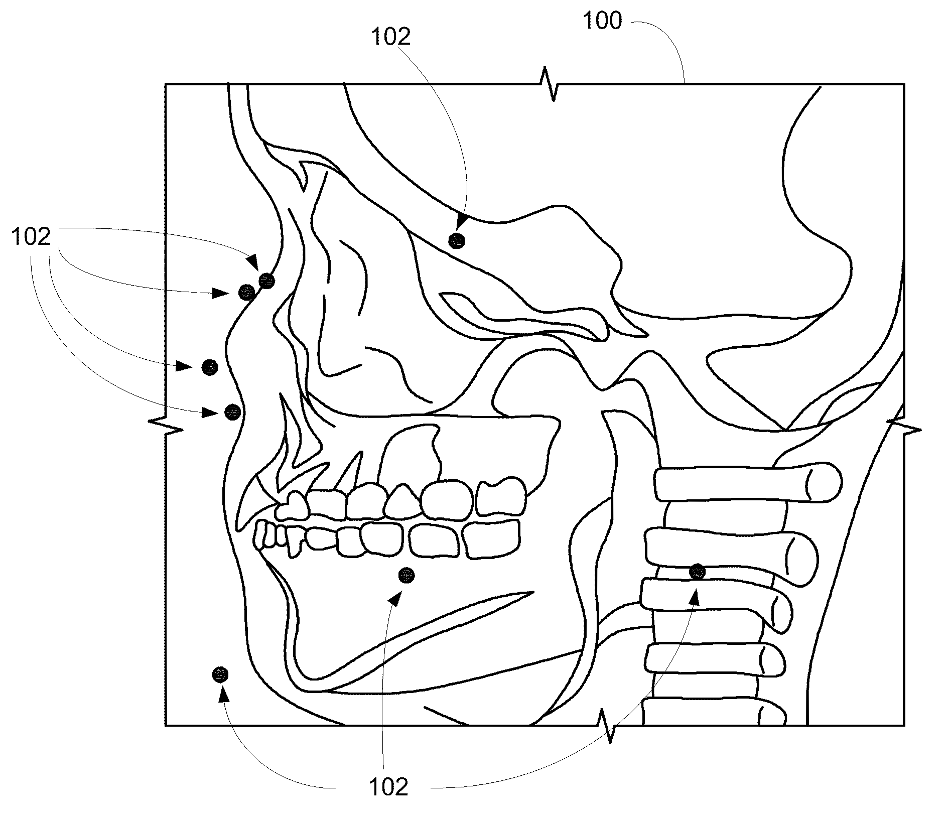
[0048]X-rays are a form of radiation similar to light rays but are rays that can penetrate the human body. When x-rays pass through a human body, however, the intensity of the x-ray decreases. The ...


PUM


Abstract

A method and system of rapidly detecting and mapping a plurality of marker points identified in a sequence of projection images to a physical marker placed on a patient or other scanned object. Embodiments of the invention allow a marker physical mapping module executable by an electronic processing unit to obtain a sequence of images based on image data generated by a scanner. Each image in the sequence of images represents an angle of rotation by the scanner and includes a plurality of marker points each having a U position and a V position. Expected U and V positions for the physical marker are calculated and a list of candidate marker points is created based on the expected positions. The images are processed and selected candidate marker points are added to a good point list.

Description

BACKGROUND[0001]Embodiments of the invention relate to image processing. In particular, embodiments provide methods and systems for detecting, localizing, and classifying marker-associated points located in x-ray images.SUMMARY[0002]Modern imaging systems acquire many images during a single procedure or scan. The images are combined using a process known as reconstruction to produce one or more images representing finite-width “slices” through a patient. Because the resulting images are often analyzed in preparation for medical or dental procedures or to properly calibrate the imaging equipment, it is important that the images be as clear as possible. However, patient movement during the scan can cause errors or blurring in the image.[0003]Markers are often placed on a patient before an imaging procedure. The markers appear on the resulting image as marker points and are used to identify particular features in the image. The marker points can also be used to correct the images for p...

Claims


Application Information

Patent Timeline
IPC IPC(8): G06K9/00
CPCG06T7/0028G06T2207/10081A61B6/583G06T2207/30204G06T2207/30036G06T7/33A61B6/032A61B6/5264A61B6/14A61B6/4085
Inventor SEBOK, DAVID
Owner DENTAL IMAGING TECH
Why Eureka
Try Eureka