Magnetic antenna, board mounted with the same, and RF tag

a technology of magnetic antenna and rf tag, which is applied in the direction of magnetic bodies, protective materials radiating elements, instruments, etc., can solve the problems of antenna sensitivity loss, and achieve the effects of less change in communication sensitivity, small size, and enhanced sensitivity

Active Publication Date: 2011-05-26
TODA IND
View PDF8 Cites 20 Cited by
  • Summary
  • Abstract
  • Description
  • Claims
  • Application Information

AI Technical Summary

Benefits of technology

[0025]The magnetic antenna of the present invention has a further enhanced sensitivity, can be used for a longer distance communication, and undergoes a less change in communication sensitivity even when coming close to and into contact with metallic objects. Therefore, the magnetic antenna can be suitably used in the applications such as 13.56 MHz RFID.
[0026]The magnetic antenna of the present invention has a small size and a high communication sensitivity and, therefore, can be suitably used in various applications such as various portable equipments, containers, metal parts, boards, metal tools and metal molds without any particular limitations to an installation space therefor.

Problems solved by technology

However, the loop antenna and electric field antenna have the following problems.
Since the magnetic field of the image has a phase opposite to that of the antenna, the sensitivity of the antenna tends to be lost.

Method used


Image

  • Magnetic antenna, board mounted with the same, and RF tag
  • Magnetic antenna, board mounted with the same, and RF tag
  • Magnetic antenna, board mounted with the same, and RF tag

Examples


examples

[0117]In the followings, the present invention is described in more detail on the basis of preferred embodiments thereof by referring to the accompanying drawings.

[Magnetic Antenna 1]

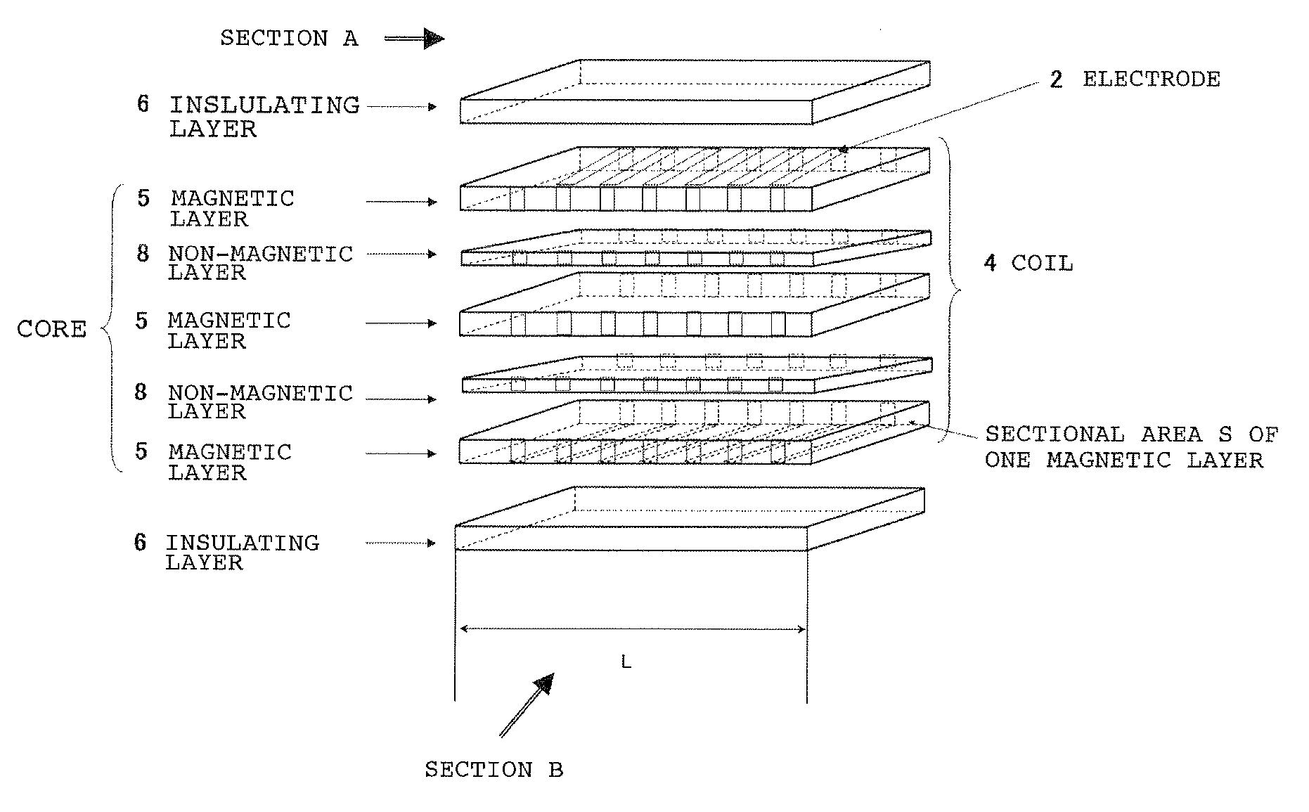
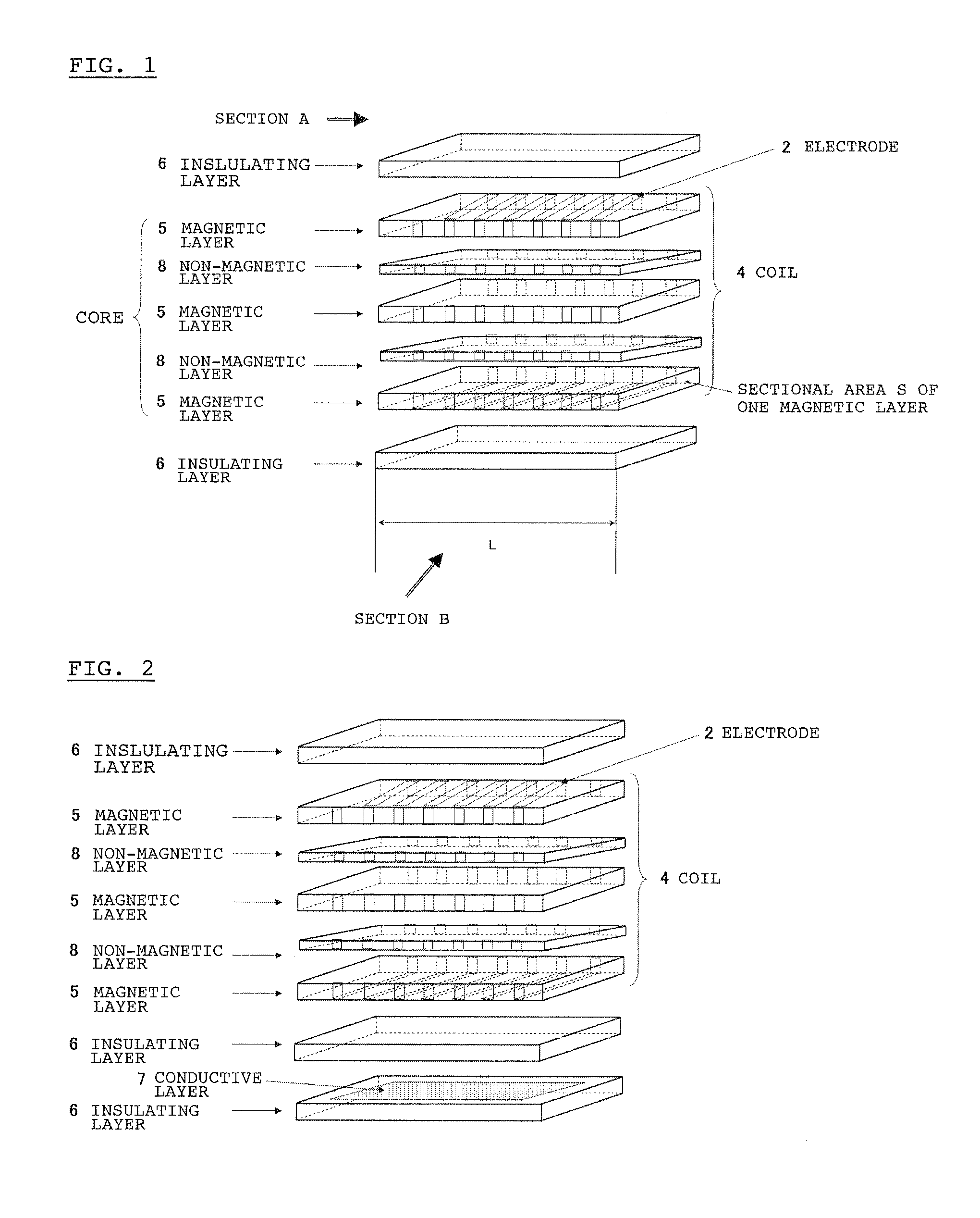
[0118]In order to form a magnetic layer (5), 100 parts by weight of calcined Ni—Zn—Cu ferrite particles which had been found to have a magnetic permeability of 13.56 MHz upon sintering at 900° C. (Fe2O3: 48.5 mol %; NiO: 25 mol %; ZnO: 16 mol %; CuO: 10.5 mol %), 8 parts by weight of a butyral resin, 5 parts by weight of a plasticizer, and 80 parts by weight of a solvent were mixed in a ball mill to prepare a slurry. The resulting slurry was applied on a PET film with a size of 150 mm×150 mm by a doctor blade such that the thickness of the coating layer obtained after sintering was 0.1 mm, thereby obtaining a sheet.

[0119]In order to form a non-magnetic layer (8), 100 parts by weight of a borosilicate glass (SiO2: 86 to 89% by weight; B2O3: 7 to 10% by weight; K2O: 0.5 to 7% by weight), 8 parts by weight...


PUM

PropertyMeasurementUnit
volume resistivityaaaaaaaaaa
total thicknessaaaaaaaaaa
thicknessaaaaaaaaaa

Abstract

The present invention relates to a magnetic antenna for information communication using a magnetic field component which is capable of satisfying both reduction in size and improvement in communication sensitivity. The magnetic antenna of the present invention is used for transmitting and receiving information using an electromagnetic induction method, and comprises a central core formed of a magnetic material and a non-magnetic material, a coil-shaped electrode material wound around the core, and an insulating layer formed on at least one outside surface of the core on which the coil-shaped electrode material is provided, in which the magnetic material is separated into two or more parts through the non-magnetic material when viewed in a section of the core which is perpendicular to a magnetic flux passing therethrough.

Description

TECHNICAL FIELD[0001]The present invention relates to a magnetic antenna for information communication using a magnetic field component, and more particularly, to a magnetic antenna which is capable of not only satisfying both reduction in size and improvement in communication sensitivity, but also transmitting and receiving a signal with a high sensitivity even when attached to a metal object without suffering from significant influences thereof.BACKGROUND ART[0002]An antenna for transmitting and receiving an electromagnetic wave using a magnetic material (hereinafter referred to merely as a “magnetic antenna”), in which a magnetic field component coming from the outside is allowed to pass through the core (magnetic material), around which a coil of a conductive wire is wound, to convert the magnetic field component into a voltage (or current) induced by the coil, has been widely used in small sized radios and TVs. Such a magnetic antenna is also used in a non-contact object identi...

Claims


Application Information

Patent Timeline
Patent Type & Authority Applications(United States)
IPC IPC(8): H04B1/38H01F38/14H01F1/22H01F17/04H01Q7/06H01Q7/08
CPCG06K19/07749G06K19/07771H01F1/344H05K2203/162H01Q1/40H01Q7/08H05K1/165H01F41/16G06K19/07H01F1/34
Inventor KOUJIMA, JUNKIMURA, TETSUYADOI, TAKANORISATO, YOSHIRO
Owner TODA IND
Why Eureka
Try Eureka