Blood flow perfusion analyzing apparatus, blood flow perfusion analyzing method, fluid analyzing apparatus and fluid analyzing method

a technology of perfusion analysis and analysis apparatus, applied in the field of blood flow perfusion analysis apparatus, blood flow perfusion analysis method, fluid analysis apparatus and fluid analysis method, can solve the problems of inapplicability change in deconvolution result, increase in analysis processing time of block circulant svd method,

Active Publication Date: 2011-06-02
TOSHIBA MEDICAL SYST CORP
View PDF7 Cites 27 Cited by
  • Summary
  • Abstract
  • Description
  • Claims
  • Application Information

AI Technical Summary

Problems solved by technology

However, a deconvolution result changes depending on a delay time which is a difference in the time direction always existing between the artery TCC and tissue TCC.
Therefore, the time of analysis processing for the block circulant SVD method increases up to over 8 times and the block circulant SVD method is not practical.
Because the technique of the non-patent document 1 does not consider the delay in the time direction with regard to the standard SVD method, the result of the deconvolution lacks a sufficient accuracy.
On the other hand, the block circulant SVD method requires much time for analysis processing though the delay in the time direction is considered.
Therefore, it is problem that both the standard SVD method and the block circulant SVD method are not practical.
Therefore, if the time for analysis processing increases, the number of examinations which can be performed decreases, a waiting time of a patient increases and the number of patients got by a certain hospital decreases.
That is, increasing the time for analysis processing brings disadvantages to both patients and hospitals.
However, a new problem occurs that the processing result depends on an offset timing since elements, which are within the head phase to the offset timing, of the tissue TCC are excluded from calculation.
Furthermore, it is difficult to identify the offset timing accurately.
As a result, it is problem that information on a blood flow perfusion cannot be obtained stably.[Non-patent document 1] Ona Wu et al, “Tracer Arrival Timing-insensitive.

Method used


Image

  • Blood flow perfusion analyzing apparatus, blood flow perfusion analyzing method, fluid analyzing apparatus and fluid analyzing method
  • Blood flow perfusion analyzing apparatus, blood flow perfusion analyzing method, fluid analyzing apparatus and fluid analyzing method
  • Blood flow perfusion analyzing apparatus, blood flow perfusion analyzing method, fluid analyzing apparatus and fluid analyzing method

Examples


first embodiment

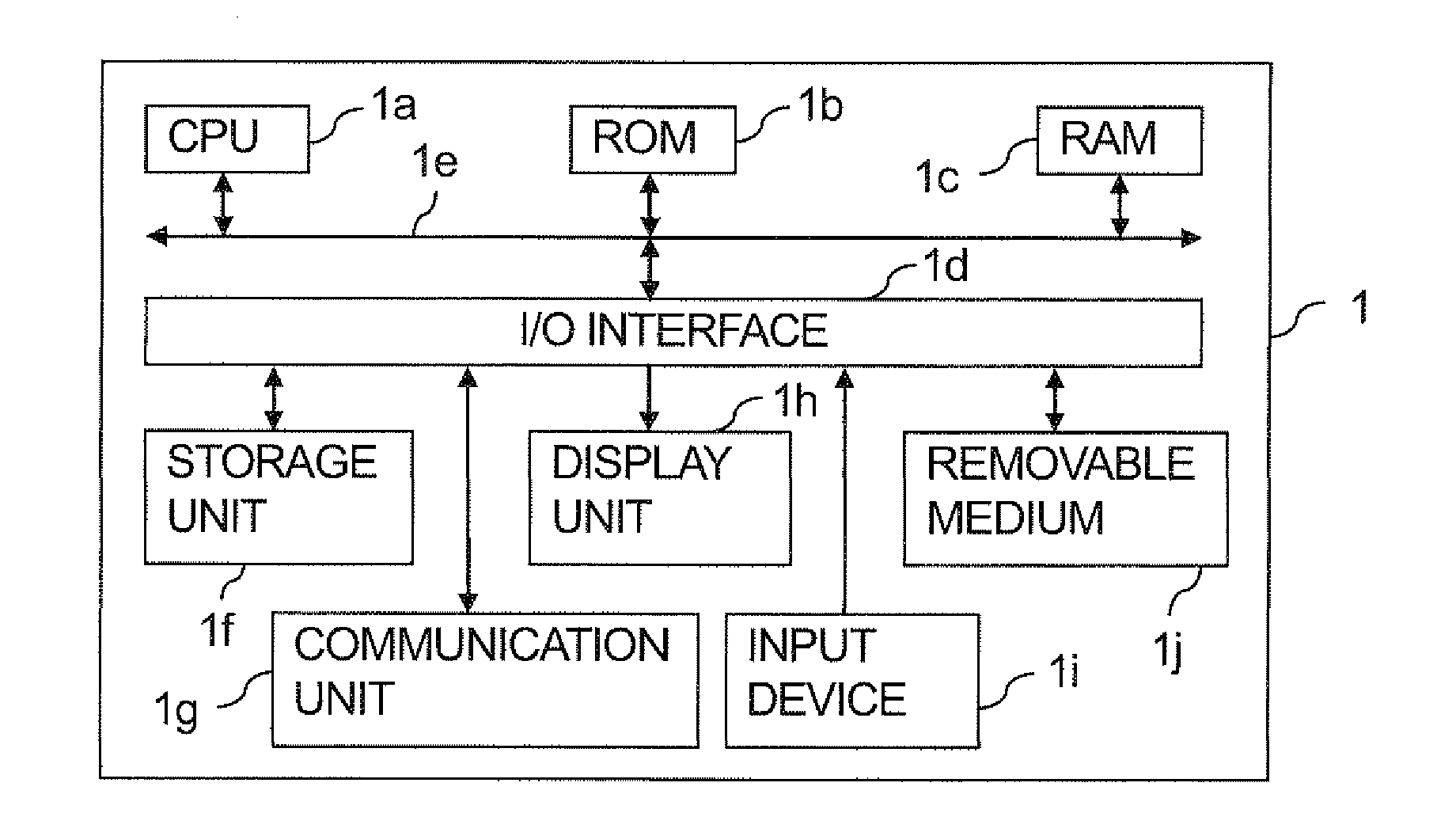
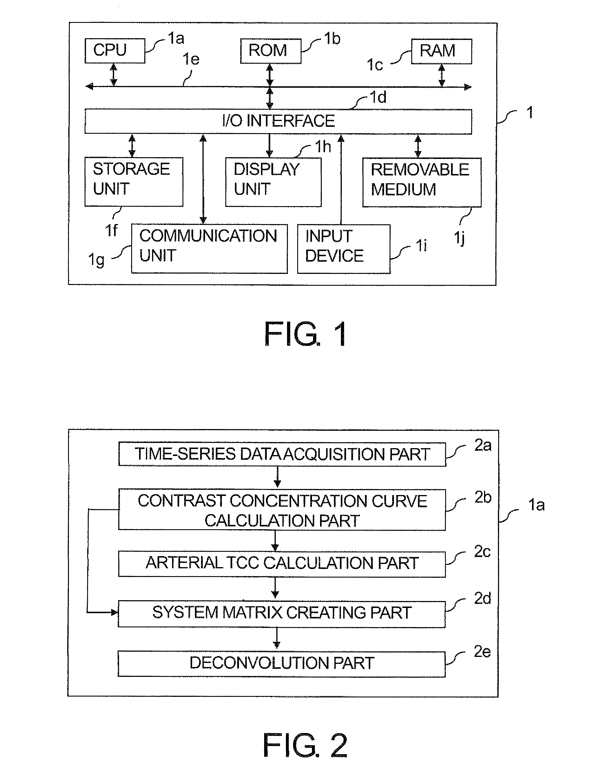
[0049]FIG. 1 is a diagram showing an example configuration of a blood flow perfusion analyzing apparatus 1 according to a first embodiment of the present invention.

[0050]A blood flow perfusion analyzing apparatus 1 includes a CPU (Central Processing Unit) 1a, a ROM (Read Only Memory) 1b, a RAM (Random Access Memory) 1c and an I / O (input / output) interface 1d mutually connected through a bus 1e. A storage unit 1f, a communication unit 1g, a display unit 1h, an input device 1i and a removable medium 1j are connected with the I / O interface 1d.

[0051]The CPU 1a reads a boot program to boot up the blood flow perfusion analyzing apparatus 1 from the ROM 1b to execute the read program based on an input signal from the input device 1i and also reads various operating systems stored in the storage unit 1f. In addition, the CPU 1a controls various targets based on input signals from the input device 1i, reads a program ordata stored in the ROM 1b or the storage unit 1f to load the read program...

second embodiment

[0124]FIG. 6 is a functional block diagram which shows a configuration example of a fluid analyzing apparatus according to a second embodiment of the present invention.

[0125]The fluid analyzing apparatus 3 is built in a MRI apparatus 4 for example. However, the fluid analyzing apparatus 3 may be connected with not only the MRI apparatus 4 but also an image processing apparatus or an image server which stores image data acquired by the MRI apparatus 4 through a network.

[0126]The MRI apparatus 4 includes an imaging part 4a. The imaging part 4 has a, function to perform non-contrast-enhanced imaging or contrast-enhanced imaging of fluid in an object to acquire pieces of non-contrast-enhanced fluid MR image data or contrast-enhanced fluid MR image data corresponding to multiple frames. Examples of fluid include blood flow in blood vessels and CSF (cerebrospinal fluid). Imaging of blood vessels by a MRI apparatus is referred to MRA (magnetic resonance angiography).

[0127]More specifically...


PUM


Abstract

According to one embodiment, a blood flow perfusion analyzing apparatus includes tissue and arterial TCC calculation units, first and second making units, a deconvolution unit and a blood flow information calculation unit. The tissue TCC calculation unit obtains tissue TCCs. The arterial TCC calculation unit calculates an arterial TCC. The first making, unit makes first sets, starting from a first time in which elements corresponding to the tissue are arrayed one-dimensionally, based on the tissue TCCs. The second making unit makes a second set, starting from a second time after the first time, in which elements corresponding to the artery are arrayed two-dimensionally, based on the arterial TCC. The deconvolution unit calculates transfer functions of the tissue based on the first and second sets. The blood flow information calculation unit calculates information on a blood flow perfusion based on the transfer functions.

Description

CROSS REFERENCES TO RELATED APPLICATIONS[0001]This application is based upon and claims the benefit of priorities from Japanese Patent Application No. 2009-270339 filed on Nov. 27, 2009 and Japanese Patent Application No. 2010-200436 filed on Sep. 8, 2010: the entire contents of Japanese Patent Application No. 2009-270339 and Japanese Patent Application No. 2010-200436 are incorporated herein by reference.BACKGROUND[0002]1. Field[0003]Embodiments described herein relate generally to a blood flow perfusion analyzing apparatus, a blood flow perfusion analyzing method, a fluid analyzing apparatus and a fluid analyzing method.[0004]2. Description of the Related Art[0005]Conventionally, an examination in which contrast medium is injected from a vein, time series image data is acquired and the image data is analyzed to obtain information on a blood flow perfusion in tissue is performed with an X-ray CT (Computed Tomography) apparatus or an MRI (Magnetic Resonance Imaging) apparatus. This ...

Claims


Application Information

Patent Timeline
Patent Type & Authority Applications(United States)
IPC IPC(8): A61B5/026
CPCA61B5/0263A61B5/027A61B5/7285A61B6/032A61B6/037A61B6/507A61B6/501A61B6/504A61B6/541G01R33/56333G01R33/56366A61B6/481
Inventor OHYU, SHIGEHARUSAKURAI, YASUO
Owner TOSHIBA MEDICAL SYST CORP
Why Eureka
Try Eureka