Waxless precision casting process

a precision casting and waxless technology, applied in the field of investment casting, can solve the problems of not being able to meet the design requirements of components, the cost of investment casting, and the inability to manufacture such blades economically with existing technology, so as to achieve the effect of improving the green body strength, facilitating the production of cores, and high failure ra

Inactive Publication Date: 2011-06-09
MIKRO SYSYTEMS INC +1
View PDF30 Cites 66 Cited by
  • Summary
  • Abstract
  • Description
  • Claims
  • Application Information

AI Technical Summary

Benefits of technology

[0013]Another enabling technology that is exploited in the present casting regiment is described in pending International Patent Application PCT / US2009 / 58220 also assigned to Mikro Systems, Inc. of Charlottesville, Va., and incorporated by reference herein. That application describes a ceramic molding composition that mimics existing ceramic core molding materials in its slurry and fully sintered condition, but that provides significantly improved green body strength when compared to the existing materials. Incorporating such an improved molding composition into the present casting regiment facilitates the production of core geometries that would not previously have survived handling in their green state without an unacceptably high failure rate. Improved green state strength is particularly important during the removal of a ceramic core from a flexible mold when the shape of a core feature is such that the mold must be deformed around the cast material in order to remove the core from the mold.
[0014]With prior art processes, the ceramic core produced as described above might then be positioned within a wax pattern mold to produce a core / wax pattern by injecting melted wax into the wax pattern mold around the ceramic core. The wax pattern would then be dipped into ceramic slurry to produce a ceramic shell around the wax to define the ceramic casting vessel. However, the waxless casting process described and claimed herein completely eliminates the use of wax and wax pattern tooling. In its place, the ceramic shell is formed directly using processes similar to those described above for the production of the ceramic core, and the ceramic shell and ceramic core are then joined together using cooperating alignment features to form the ceramic casting vessel without the need for any wax pattern. It is well known that the wax pattern production and wax injection processes are expensive and time consuming, and that yield rates are adversely affected by damage to the ceramic core associated with the wax injection process. By eliminating the use of wax completely, the present waxless casting process offers the potential for cost, schedule and yield rate improvements when compared to traditional lost-wax investment casting techniques. Furthermore, a ceramic casting vessel produced by the present method can be designed to have engineered exterior geometric features that enhance its functionality when compared to the featureless blob shape produced by the prior art dipping process. Details of the waxless precision casting process and other advantages over the prior art are disclosed below.

Problems solved by technology

No such blade has heretofore been produced, nor is it believed that such a blade can be produced economically with existing technology.
However, due to the projected size of these new blades and the intricacy of the desired cooling passages, the ceramic cores that would be necessary for investment casting of such cooling passages are beyond the commercially practical capabilities of existing investment casting processes.
This new regiment not only extends and refines existing capabilities, but it also provides new and previously unavailable design practicalities for the component designer.

Method used


Image

  • Waxless precision casting process
  • Waxless precision casting process
  • Waxless precision casting process

Examples


Embodiment Construction

Exemplary Casting Process

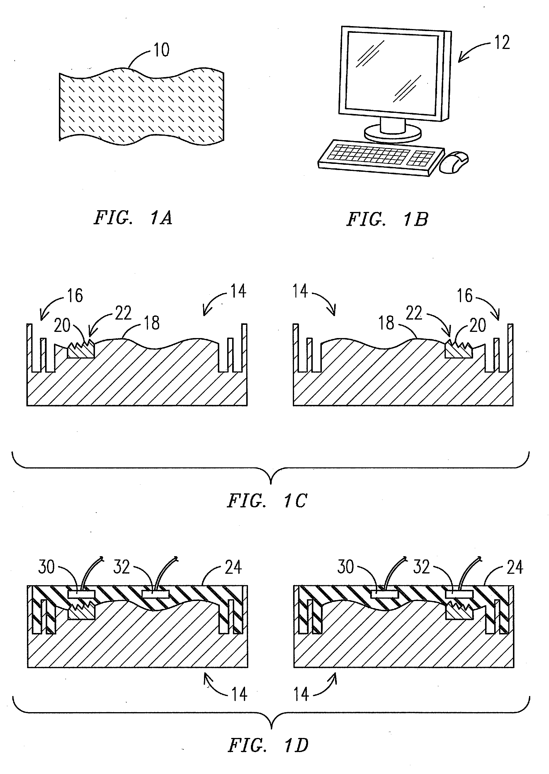
[0027]The waxless precision casting process disclosed herein includes the use of relatively inexpensive master tools made from easily machined soft alloy material, such as aluminum, with optional high precision feature inserts. The master tools are used to cast intermediate flexible molds, which in turn are used to cast respective sections of a ceramic casting vessel. The vessel sections are then assembled to form a complete ceramic casting vessel, with precise alignment of the sections facilitated by cooperating alignment features.

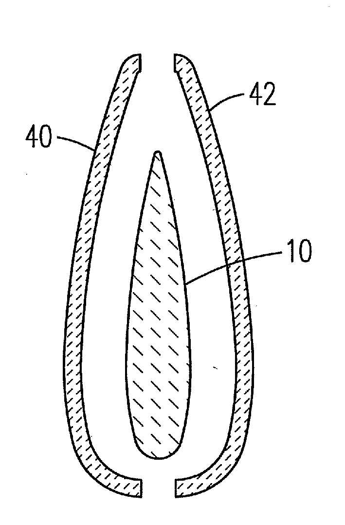
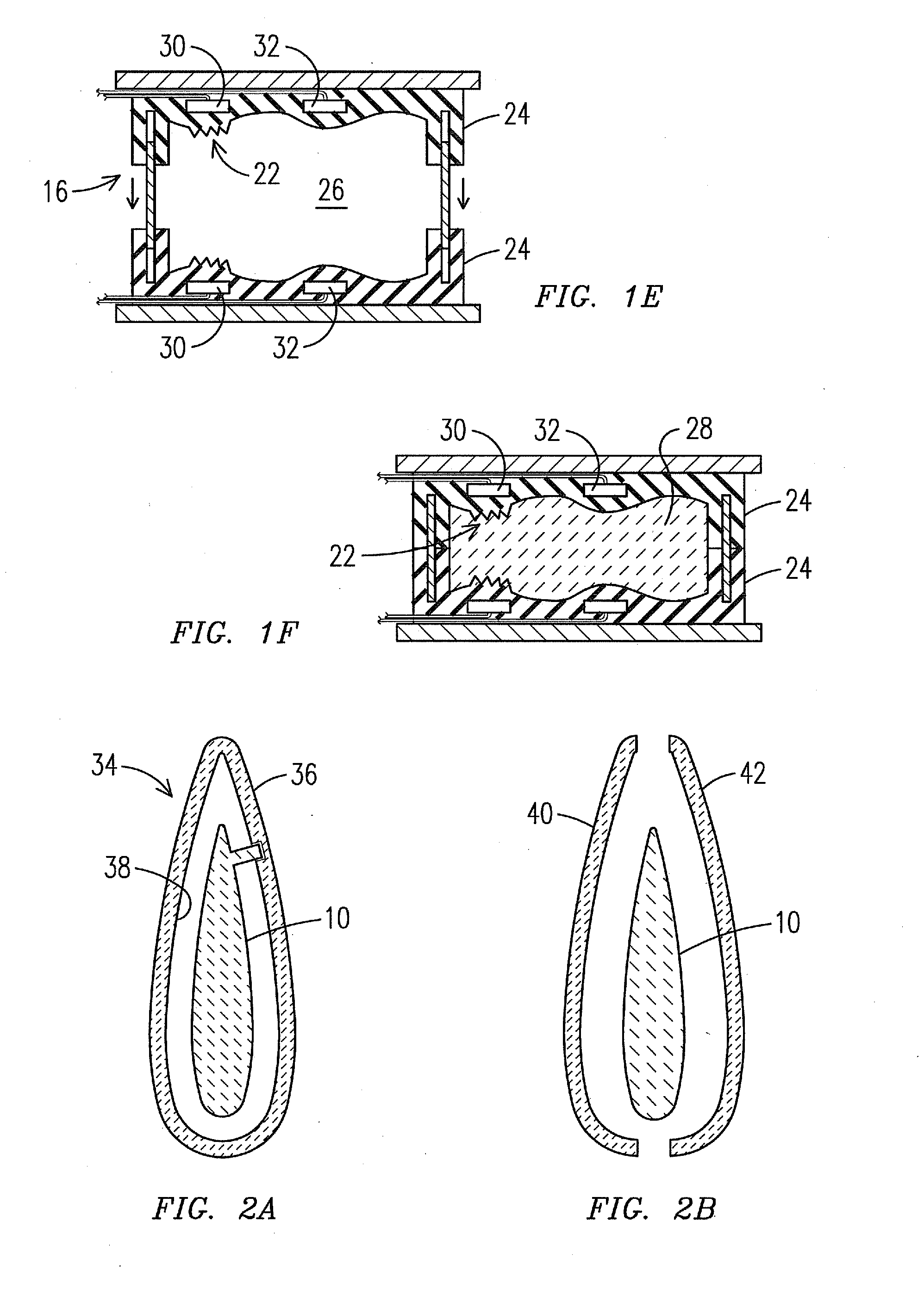
[0028]An exemplary embodiment of the invention discussed herein is the fabrication of a gas turbine blade, which is a hollow alloy component having interior cooling passages; however, one will appreciate that the invention is not so limited and may be used for the fabrication of various hollow and solid components. The present waxless casting process is first described in part under this subheading with reference made to the fabri...


PUM

PropertyMeasurementUnit
lengthaaaaaaaaaa
pressureaaaaaaaaaa
porosityaaaaaaaaaa

Abstract

Alloy products are produced with a waxless casting process. A model of a ceramic casting vessel (34) defining a desired product shape is digitally divided into sections (10, 40, 42). Each section is translated into a soft alloy mater tool (14) including precision inserts (20) where needed for fine detail. A flexible mold (24) is cast from each master tool, and a section of the ceramic casting vessel is cast from the respective flexible mold. The vessel sections are assembled by aligning cooperating precision features (58, 60) cast directly into each section and the alloy part is cast therein. No wax or wax pattern tooling is needed to produce the cast alloy product. Engineered surface features (54) may be included on both the interior and exterior surfaces of the shell sections.

Description

[0001]This application claims benefit of the 8 Dec. 2009 filing date of U.S. provisional patent application No. 61 / 267,717, the entire disclosure of which is incorporated by reference herein.FIELD OF THE INVENTION[0002]This invention relates to the field of investment casting.BACKGROUND OF THE INVENTION[0003]Investment casting is one of the oldest known alloy-forming processes, dating back thousands of years to when it was first used to produce detailed artwork from alloys such as copper, bronze and gold. Industrial investment castings became more common in the 1940's when World War II increased the demand for precisely dimensioned parts formed of specialized alloy alloys. Today, investment casting is used in the aerospace and power industries to produce gas turbine components such as blades having complex airfoil shapes and internal cooling passage geometries.[0004]The production of a gas turbine blade using the prior art investment casting process (also called lost-wax casting) in...

Claims


Application Information

Patent Timeline
Patent Type & Authority Applications(United States)
IPC IPC(8): B22C9/12B22D19/00B22C9/10
CPCB22C9/02B22C9/103B22C9/24B22C7/06B22C9/10B22C9/22B22C9/04
Inventor MERRILL, GARY B.APPLEBY, MICHAEL P.FRASER, IAIN A.KLINGER, JILLPAULUS, JOHN R.
Owner MIKRO SYSYTEMS INC
Why Eureka
Try Eureka