
Heavy oil cracking method

a heavy oil and cracking technology, applied in the petroleum industry, hydrocarbon oil treatment, hydrotreatment process, etc., can solve the problems of increasing the feed heating rate, reducing capital cost, and none of these processes fully meeting all these criteria, so as to improve the solubility of coke precursors, inhibit secondary cracking, and improve the control of reactor composition

Inactive Publication Date: 2011-06-09
LINDE AG
View PDF26 Cites 0 Cited by
  • Summary
  • Abstract
  • Description
  • Claims
  • Application Information

AI Technical Summary

Benefits of technology

[0012]The invention provides for advantages to the process of converting residual heavy oil. The invention improves control over the reactor composition. The staging process provides for prompt removal of cracked distillate product to inhibit secondary cracking and increases the solubility of coke precursor in the liquid phase. Thermal efficiencies are also realized by the invention.

Problems solved by technology

Not only do such processes increase the yields of the more valuable liquid and gaseous products, but more compact designs would also decrease capital costs.
However, none of these processes fully meet all these criteria while treating asphaltic residual oils.
The FCC feed nozzles improve the uniformity of the initial contact between the carbonaceous feed and the hot regenerated catalyst, which increases the feed heating rate and decreases the yield of the undesirable dry gas and coke FCC produces.
The higher coke yield associated with more asphaltic residual FCC feeds has a large adverse effect on the process performance.
Canadian Patent No. 2,369,288, teaches thermal cracking of residual oil feed with inert solids in an FCC reactor-type short contact time reactor to eliminate catalyst deactivation problems, but also results in an inferior product yield distribution, including coke production in excess of the process heat requirement.
Despite these efforts to decrease the FCC process coke yield with residual asphaltic feeds, the coke yield far exceeds the amount required to preheat the regenerated catalyst or inert solids.
Since both the fluid coking and FCC processes require that all liquid products are produced by vaporization, neither process can operate with a short residence time for unconverted asphaltic residual oils.
In addition, the solvent and residual oil separation steps have a significant steam heat requirement.
Unfortunately, the earlier processes do not provide any method that can heat the bitumen feed, separate the deasphalted oil and asphaltene products, and cool the separated deasphalted oil and asphaltene products sufficiently rapidly to avoid excessive thermal cracking and degradation of the deasphalted oil product.
U.S. Pat. No. 4,427,535 identifies a fundamental limitation with this approach.
These high temperature and short contact time benefits seem to be only limited by the practical limits on the feed heating rate and the product cooling rate.

Method used


Image

  • Heavy oil cracking method
  • Heavy oil cracking method
  • Heavy oil cracking method

Examples


Embodiment Construction

[0030]The invention will now be described in more detail and with reference to the drawing figures.

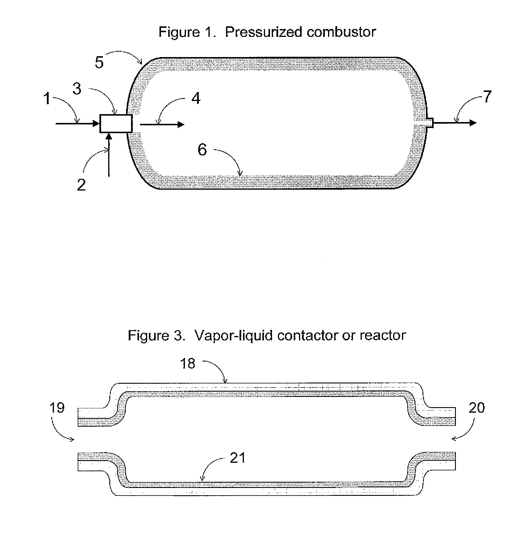
[0031]The pressurized combustor on FIG. 1 mixes a fuel 1 with an oxidant 2 in a burner 3. The fuel may be any hydrocarbon and / or hydrogen. The fuel is preferably a H2 and CO synthesis gas that is produced by conventional gasification of the pitch by-product (see Stream 40 on FIG. 5). The oxidant 2 may be any mixture of air, O2, and steam. The burner 3 utilizes conventional ignition and flame monitoring methods to maintain a stable flame 4. The combustion reactions are substantially completed within a pressurized shell 5. The pressurized shell 5 may be advantageously fitted with internal insulation 6 to decrease heat loss and the pressurized combustor shell 5 temperature. The pressurized combustor product gas 7 would typically be in the 5 to 20 bar pressure range, 1400-1800° C. temperature range, and 0 to −5% excess O2.

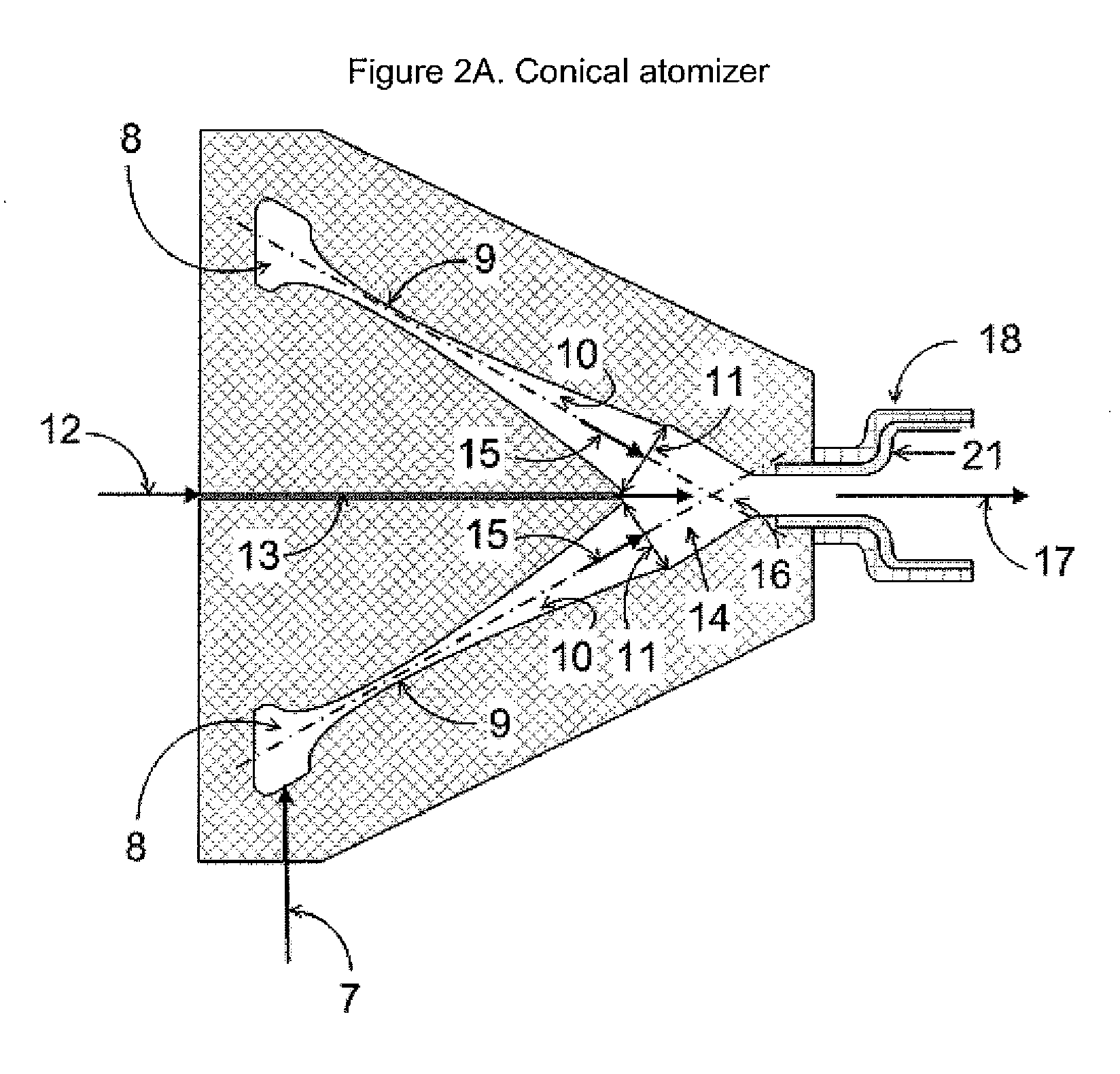
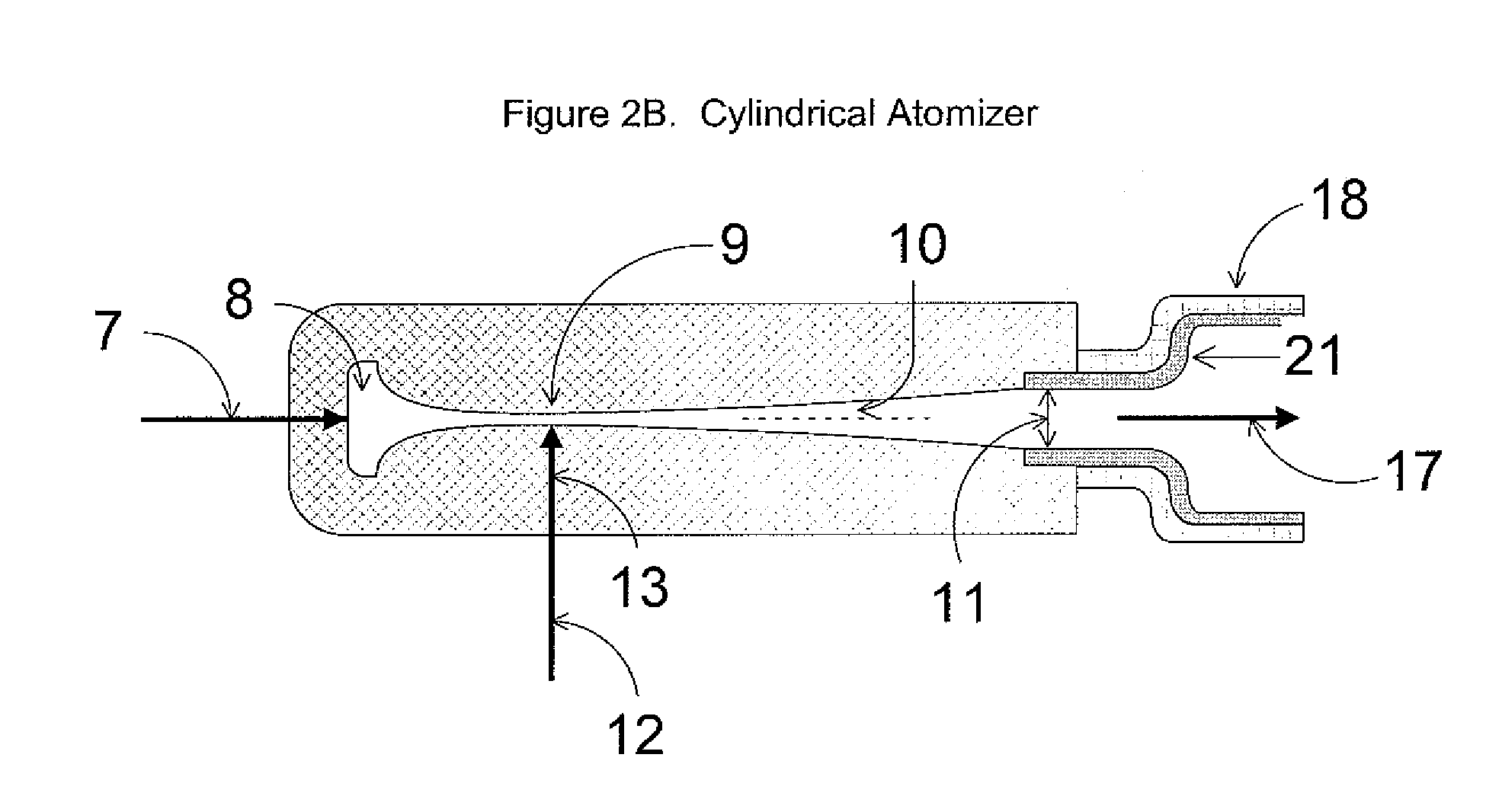
[0032]Typical heavy oil atomizers are illustrated on FIGS. 2A and 2B...


PUM


Abstract

A method for cracking heavy oil is disclosed. The method uses a first heating stage, a second heating stage, a first cracking stage and a second cracking stage to produce cracked distillates from the residual heavy oil.

Description

CROSS REFERENCE TO RELATED APPLICATIONS[0001]This application claims priority from U.S. Provisional Application Ser. No. 61 / 223,885 filed Jul. 8, 2009.BACKGROUND OF THE INVENTION[0002]The invention is directed to a method for cracking heavy oil. More particularly, the invention is directed to a method for cracking heavy oil using staging to convert the heavy oil feed to a cracked pitch product.[0003]A recent review article [Hulet (2005)] examined the key features and configurations of short residence time cracking processes developed over the past 25 years. This work succinctly summarized the promise, key features, and challenges of short residence time processes:“There is a strong economic incentive for considering short residence time cracking processes. Not only do such processes increase the yields of the more valuable liquid and gaseous products, but more compact designs would also decrease capital costs. Careful control of the vapor residence times appears to be crucial in ord...

Claims


Application Information

Patent Timeline
IPC IPC(8): C10G51/02
CPCC10G51/02
Inventor SATCHELL, JR., DONALD PRENTICEGORSKI, CHET
Owner LINDE AG
Learn More