Multi-segment anode target for an x-ray tube of the rotary anode type with each anode disk segment having its own anode inclination angle with respect to a plane normal to the rotational axis of the rotary anode and x-ray tube comprising a rotary anode with such a multi-segment anode target

a technology of x-ray tubes and anodes, which is applied in the direction of x-ray tube target geometry, electric discharge tubes, electrical apparatus, etc., can solve the problems of high energy density at the focal spot, the power limiting factor of high-power x-ray sources, and the melting temperature of anodes

Inactive Publication Date: 2011-06-09
KONINKLIJKE PHILIPS ELECTRONICS NV
View PDF5 Cites 47 Cited by
  • Summary
  • Abstract
  • Description
  • Claims
  • Application Information

AI Technical Summary

Benefits of technology

[0018]A second exemplary embodiment of the present invention relates to an X-ray tube of the rotary anode type which comprises a rotatably supported multi-target anode for emitting X-radiation when being exposed to an electron beam incident on a surface of a respective one from a plurality of distinct anode targets. According to this embodiment, said multi-target anode has a geometrical form which is given by a solid of revolution of a multi-segment structure comprising a number of conical anode segments inclined by distinct inclination angles with respect to a plane normal to the rotational axis of said rotary anode such that each anode target has its own focal track width and emits a fan X-ray beam with a field of view of its own size as given by the own angle of inclination of the conical anode segment and the opening angle of said X-ray beam.
[0019]Similar to said first exemplary embodiment, said X-ray tube may comprise at least one focusing unit for focusing the electron beam on the position of a focal spot on an anode target of said X-ray tube's rotary multi-target anode and a focusing control unit for adjusting the focusing of the focal spot such that deviations in the focal spot size relative to a given nominal focal spot size are compensated.
[0020]In addition to that, at least one deflection unit for generating an electric and / or magnetic field deflecting the electron beam in radial direction of the rotary multi-target anode may be provided as well as a deflection control unit for adjusting the strength and / or algebraic sign of the electric and / or magnetic field such that deviations in the focal spot position relative to a nominal focal spot position on a circular focal track of a given width, said width depending on the inclination angle of the respective anode segment, are compensated. The at least one focusing unit and the at least one deflection unit may thereby be realized as a combined multi-pole focusing and deflection electrode system and / or as a combined multi-pole focusing and deflection coil or magnet system, respectively.
[0021]A third exemplary embodiment of the present invention refers to an X-ray scanner system which comprises an X-ray tube of the rotary anode type as described above with reference to said first or second exemplary embodiment.

Problems solved by technology

Today, one of the most important power limiting factor of high power X-ray sources is the melting temperature of their anode material.
At the same time, a small focal spot is required for high spatial resolution of the imaging system, which leads to very high energy densities at the focal spot.
Unfortunately, most of the power which is applied to such an X-ray source is converted into heat.
Consequently, the anode of a high power X-ray source carries an extreme heat load, especially within the focus (an area in the range of about a few square millimeters), which would lead to the destruction of the tube if no special measures of heat management are taken.
Efficient heat dissipation thus represents one of the greatest challenges faced in the development of current high power X-ray sources.
However, as the anode is now rotating in a vacuum, the transfer of thermal energy to the outside of the tube envelope depends largely on radiation, which is not as effective as the liquid cooling used in stationary anodes.
Another difficulty associated with rotary anodes is the operation of a bearing system under vacuum and the protection of this system against the destructive forces of the anode's high temperatures.
In the early days of rotary anode X-ray sources, limited heat storage capacity of the anode was the main hindrance to high tube performance.
High-speed image generation, however, requires high peak power performance of the respective X-ray source.

Method used


Image

  • Multi-segment anode target for an x-ray tube of the rotary anode type with each anode disk segment having its own anode inclination angle with respect to a plane normal to the rotational axis of the rotary anode and x-ray tube comprising a rotary anode with such a multi-segment anode target
  • Multi-segment anode target for an x-ray tube of the rotary anode type with each anode disk segment having its own anode inclination angle with respect to a plane normal to the rotational axis of the rotary anode and x-ray tube comprising a rotary anode with such a multi-segment anode target
  • Multi-segment anode target for an x-ray tube of the rotary anode type with each anode disk segment having its own anode inclination angle with respect to a plane normal to the rotational axis of the rotary anode and x-ray tube comprising a rotary anode with such a multi-segment anode target

Examples


Embodiment Construction

[0028]In the following, an X-ray tube's rotary anode target according to an exemplary embodiment of the present invention will be explained in more detail with respect to special refinements and referring to the accompanying drawings.

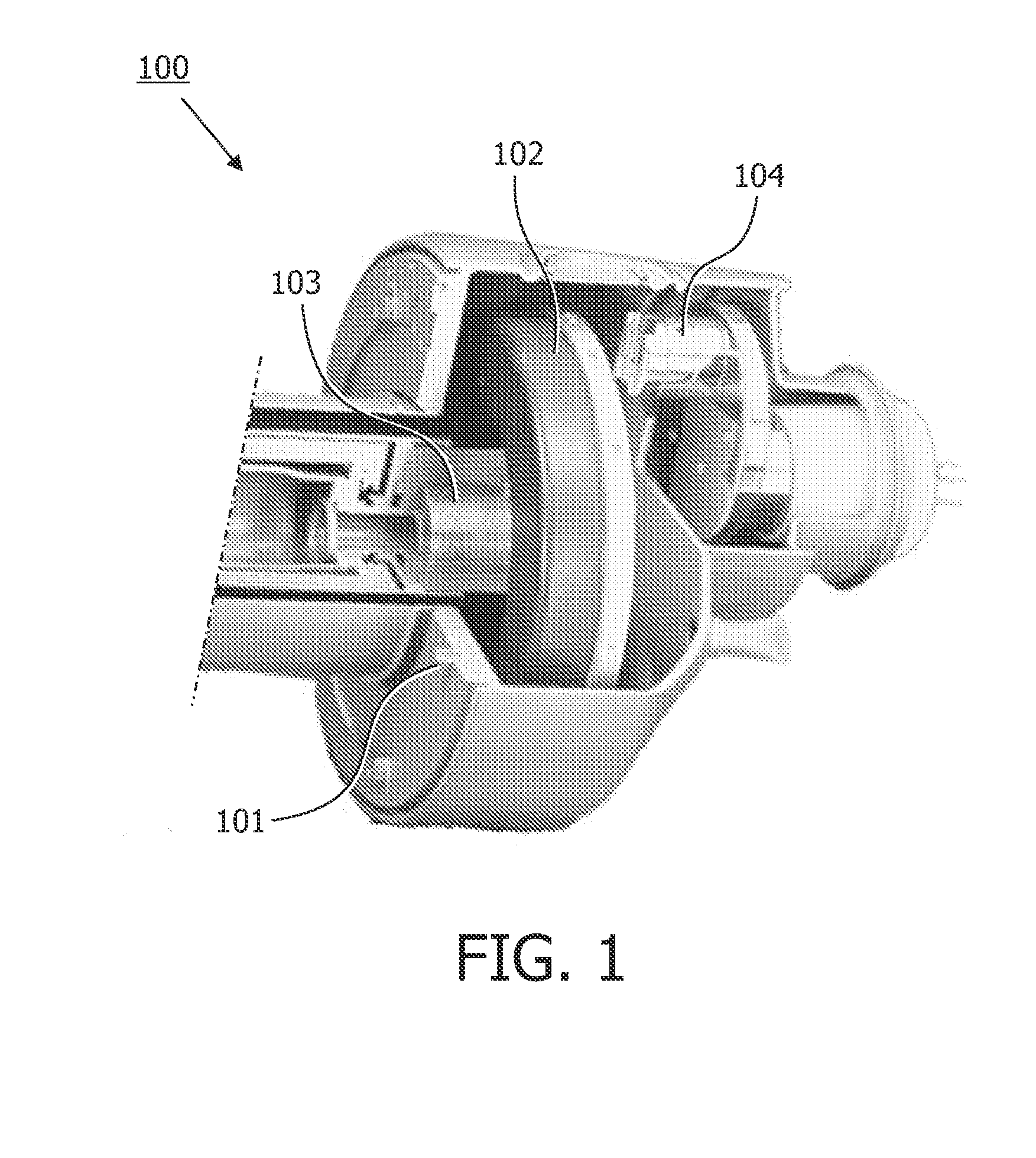
[0029]The focal spot of an X-ray tube's anode emits X-radiation into a half sphere around the anode. As can be taken from FIG. 1, which shows a three-dimensional view of a conventional X-ray tube of the rotary anode type as known from the prior art with a rotationally supported anode fixedly attached to a rotary shaft 103, an X-ray beam which is emitted by the anode target of the rotary anode 102 when being exposed to an electron beam emitted by a cathode 104 may be limited by anode shadow, the radiation port of the X-ray tube, the radiation port of the tube housing 101 and by the blades of an additional aperture.

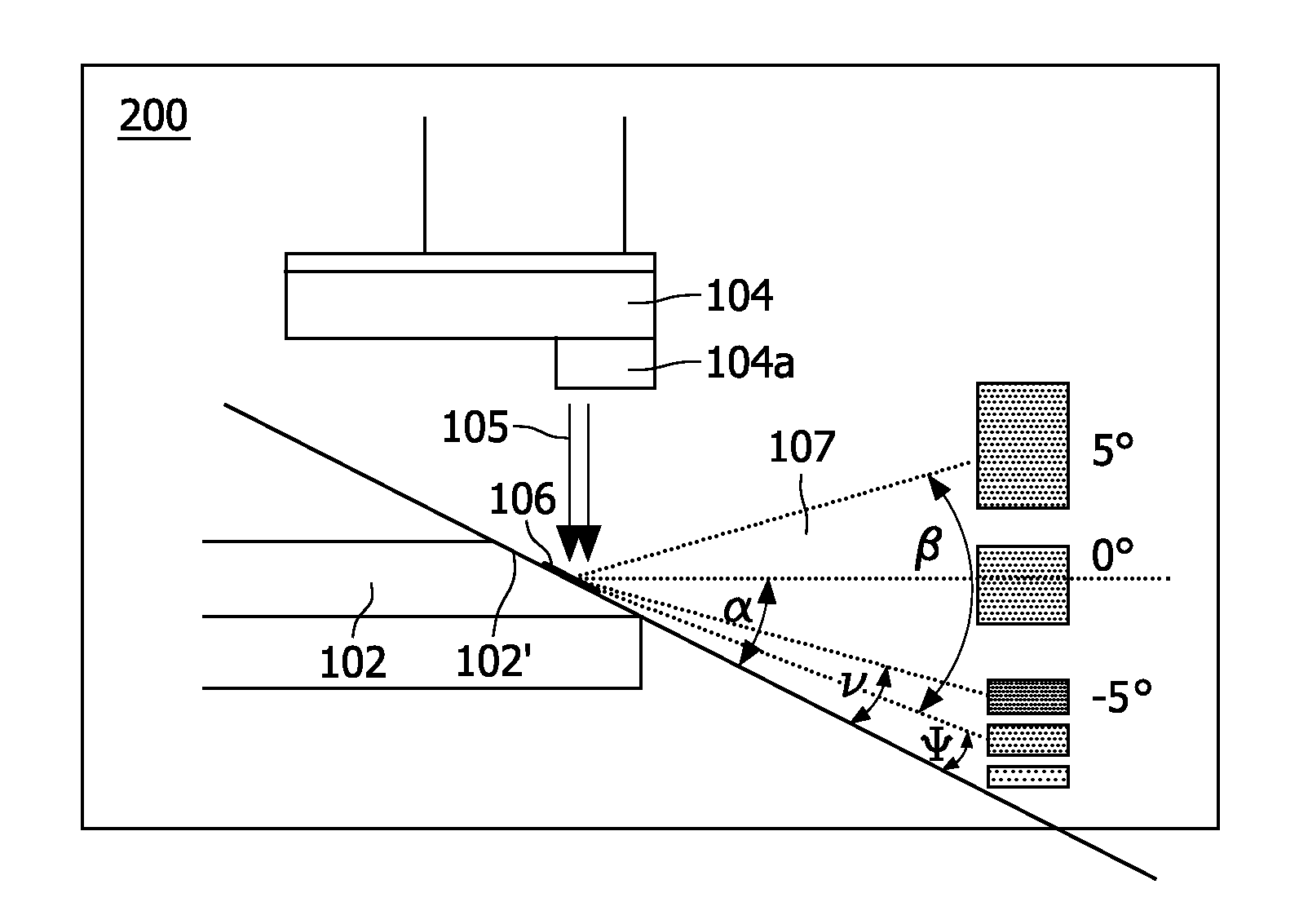
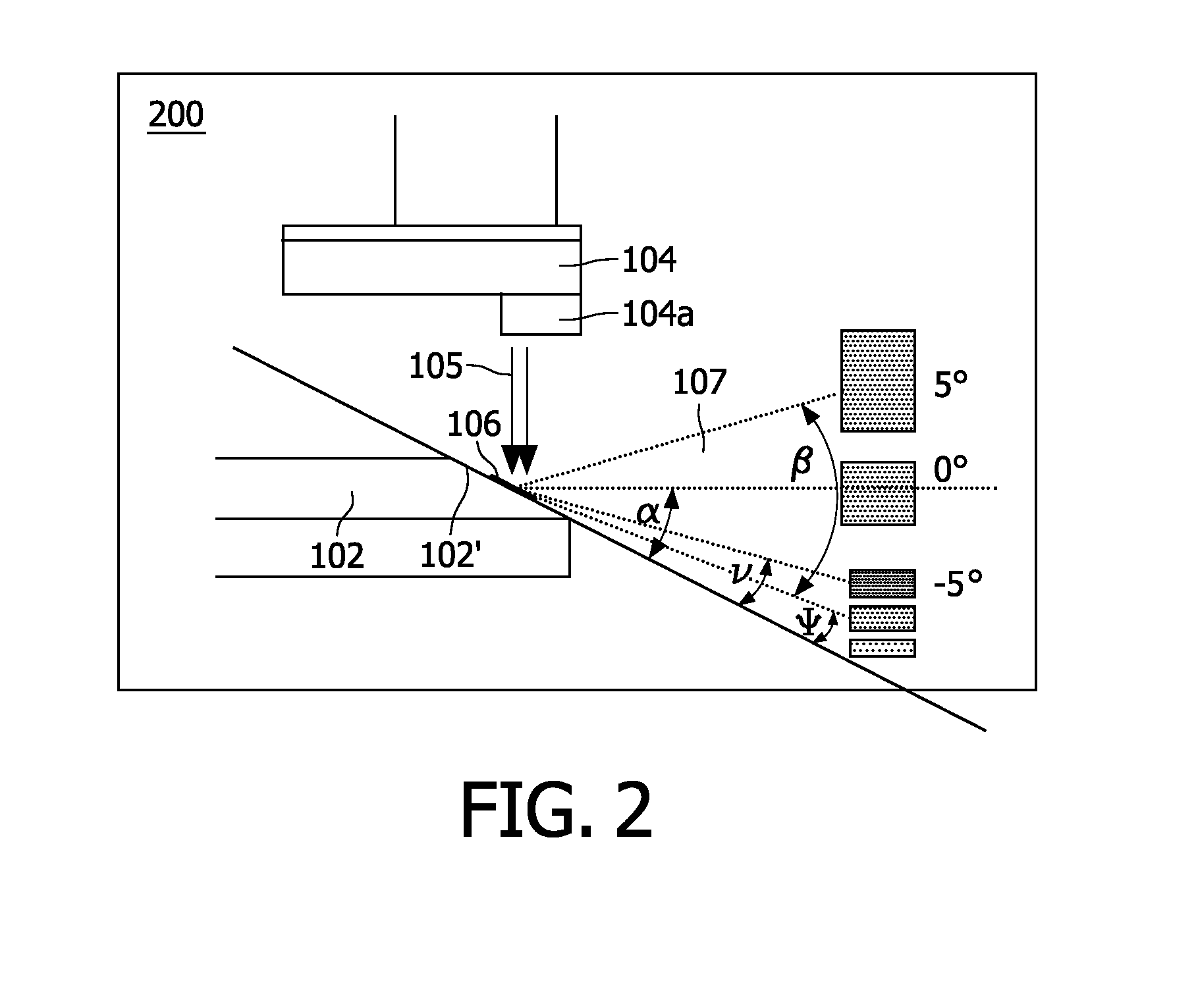
[0030]The impact of the anode inclination angle on the radiation field of an emitted X-ray beam can be derived from FIG. 2. As shown in this f...


PUM


Abstract

The present invention refers to X-ray tubes for use in imaging applications with an improved power rating and, more particularly, to a multi-segment anode target (102′) for an X-ray based scanner system using an X-ray tube of the rotary anode type, said X-ray tube comprising a rotatably supported essentially disk-shaped rotary anode (102) with an anode target (102′) for emitting X-radiation when being exposed to an electron beam (105a) incident on a surface of said anode target (102′), wherein said rotary anode disk (102) is divided into at least two anode disk segments (102a and 102b) with each of said anode disk segments having a conical surface inclined by a distinct acute angle (α) with respect to a plane normal to the rotational axis (103a) of said rotary anode disk (102) and thus having its own focal track width. A control unit for pulsing the electron beam (105a) is provided which is adapted for pulsing the electron beam (105a) such that the electron beam has a duty cycle which takes on its switched on state only when incident on a selectable anode disk segment (102a or 102b) with an inclination angle (α) from a given angular range or on a anyone from a selectable set of these anode disk segments (102a or 102b). Controlling the electron beam's pulse sequence thereby allows to select the optimal segment of the focal spot track (106b) with the smallest possible inclination angle (α) dependent on the angular size (β) of a desired field of view and helps to achieve a maximum brightness of the focal spot (106) as well as a maximized power rating. An advantage of the invention consists in an enhanced image quality compared to conventional rotary anodes as known from the prior art.

Description

[0001]The present invention refers to X-ray tubes for use in imaging applications with an improved power rating and, more particularly, to a multi-segment anode target for an X-ray based scanner system using an X-ray source of the rotary anode type, wherein said anode target is divided into two or more anode disk segments with each of said anode disk segments having its own inclination angle with respect to a plane normal to the rotational axis of the rotary anode. An electron beam incident on the inclined surface of the rotary anode is pulsed such that the electron beam is in a switched on state when the anode disk segment with the smaller inclination angle passes said electron beam. Vice versa, said electron beam is in a switched off state when the anode disk segment with the larger inclination angle passes said electron beam.BACKGROUND OF THE INVENTION[0002]Conventional high power X-ray tubes typically comprise an evacuated chamber which holds a cathode filament through which a h...

Claims


Application Information

Patent Timeline
Patent Type & Authority Applications(United States)
IPC IPC(8): H01J35/14
CPCH01J2235/086H01J35/10
Inventor BEHLING, ROLF KARL OTTO
Owner KONINKLIJKE PHILIPS ELECTRONICS NV
Why Eureka
Try Eureka