Gas turbine plant

a technology of gas turbines and plants, applied in the direction of machines/engines, stators, liquid fuel engines, etc., can solve problems such as operating limitations, achieve the effects of reducing the metal temperature of the blade ring, improving the working efficiency of the gas turbine, and reducing the clearance of the tip

Active Publication Date: 2011-06-09
MITSUBISHI HEAVY IND LTD
View PDF8 Cites 46 Cited by
  • Summary
  • Abstract
  • Description
  • Claims
  • Application Information

AI Technical Summary

Benefits of technology

[0021]This gas turbine plant includes the air system used to cool the second-stage turbine stator blades, and the first-stage segmented ring and the second-stage segmented ring that oppose the tips of first-stage turbine rotor blades and second-stage turbine rotor blades are supported by the same blade ring member. The cooling-air for the second-stage turbine stator blades forms a cooling air flow cooling the blade ring member, and the flow path switching means for the cooling air is provided in the cooling-air flow path to switch the flow path used during start-up, in which high-temperature compressed air introduced from the compressor outlet is used as the cooling air, and the flow path used during load operation, in which high-pressure bleed air introduced from the high-pressure stage of the compressor is used as the cooling air. Accordingly, it is possible to perform active clearance control for ensuring the tip clearance of the first-stage turbine rotor blades during start-up by a heating operation using high-pressure, high-temperature compressed air and for reducing the tip clearance during loa

Problems solved by technology

However, the conventional ACC has a problem in that there are operational limitations, because steam has to

Method used


Image

  • Gas turbine plant
  • Gas turbine plant
  • Gas turbine plant

Examples


first embodiment

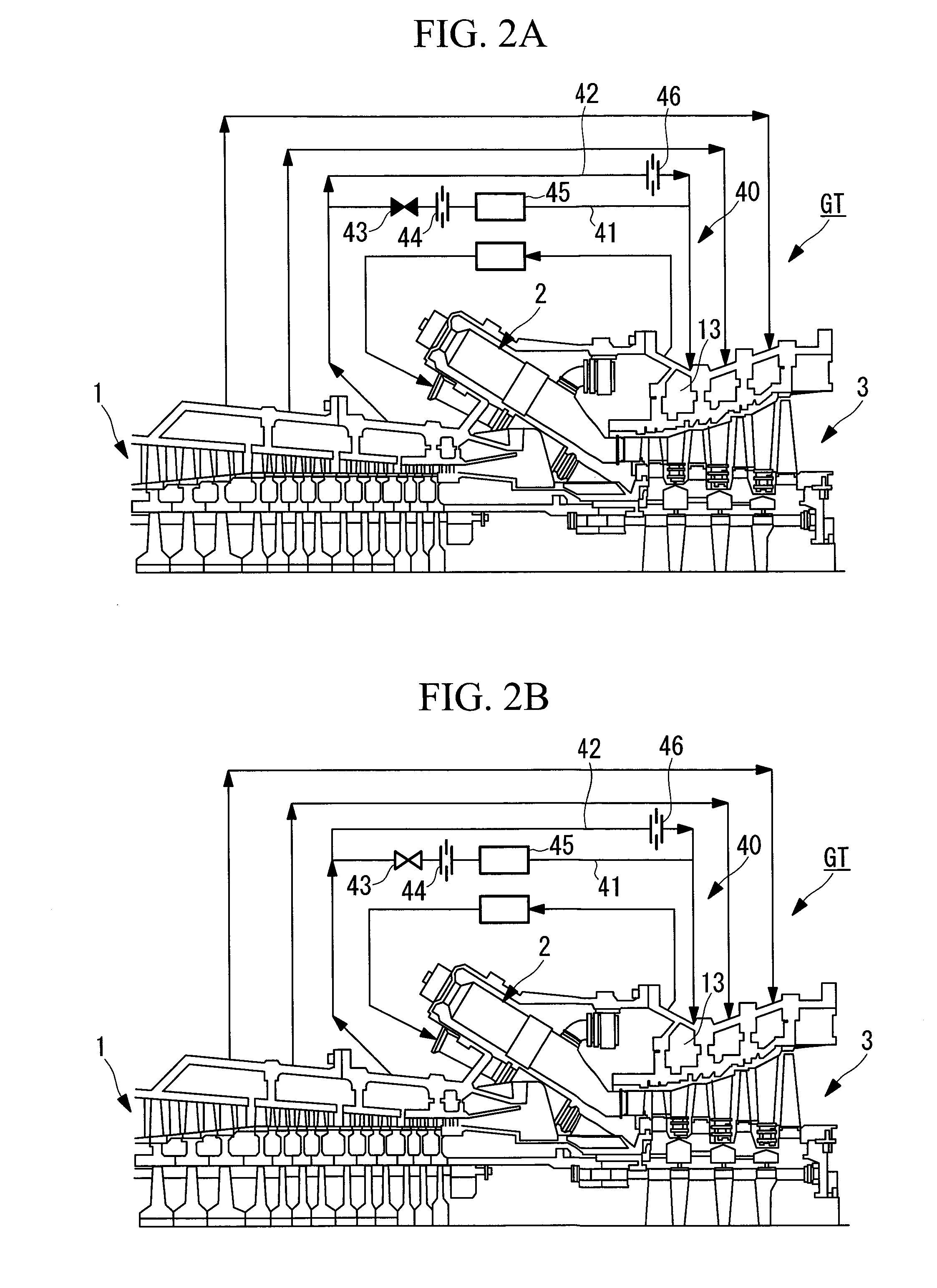
[0056]A gas turbine GT shown in FIGS. 2A and 2B includes a compressor 1, a combustor 2, and a turbine unit 3. In this gas turbine GT, air compressed by the compressor 1 is supplied to the combustor 2, and fuel is combusted using the compressed air in the combustor 2. When the thus-produced high-pressure, high-temperature combustion gas is supplied to the turbine unit 3, the combustion gas flows between stator blades and rotor blades of the turbine unit 3, whereby, for example, the thermal energy of the combustion gas can be extracted as shaft output.

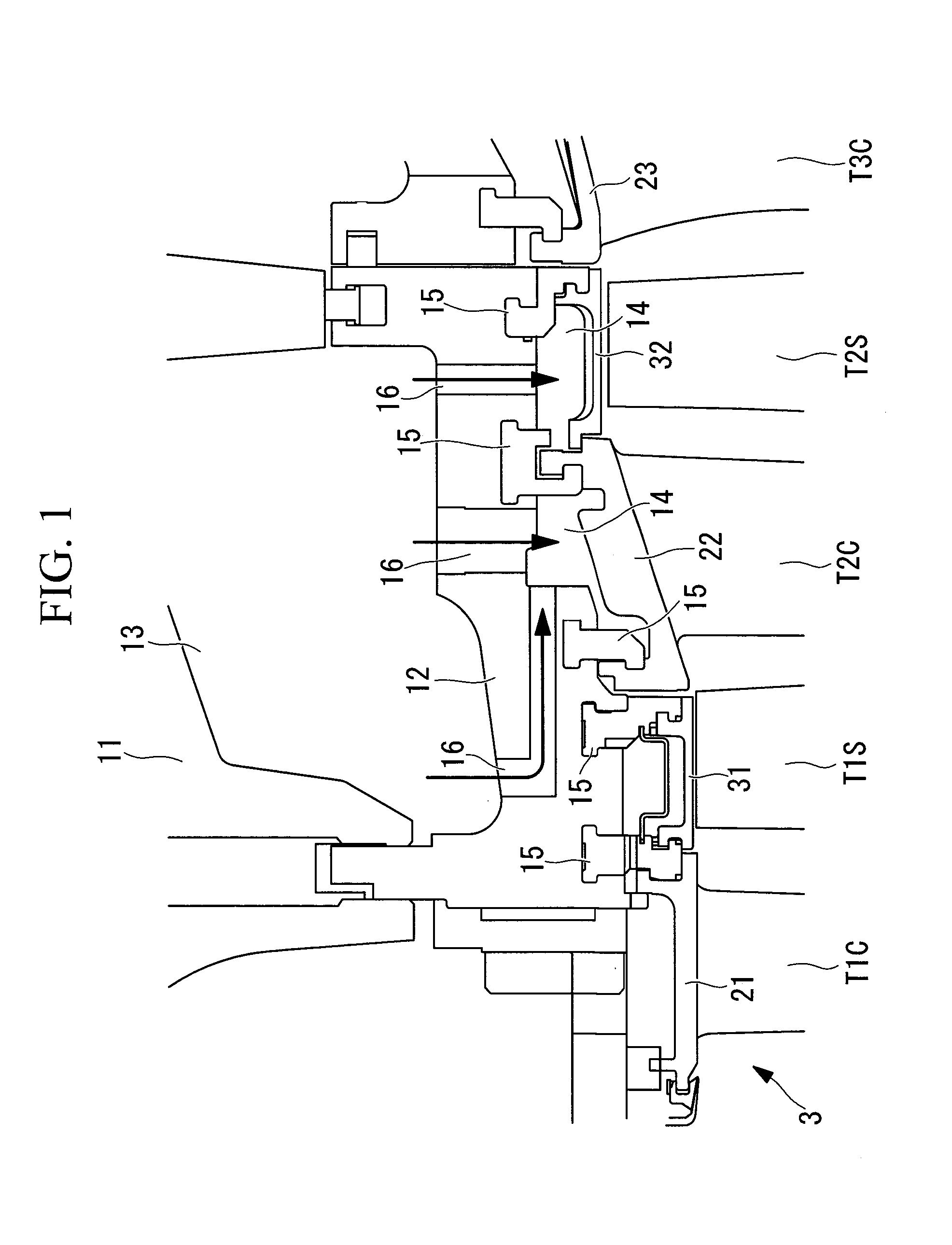
[0057]FIG. 1 is a partial sectional view showing the inlet of the turbine of the gas turbine GT. Turbine rotors rotate in a casing including an outer casing 11 and a blade ring 12 by allowing the high-pressure, high-temperature combustion gas supplied from the combustor 2 to flow therein.

[0058]The cylindrical blade ring 12 has, in sequence from the upstream side in the flow direction of the combustion gas, a plurality of stages of turbin...

second embodiment

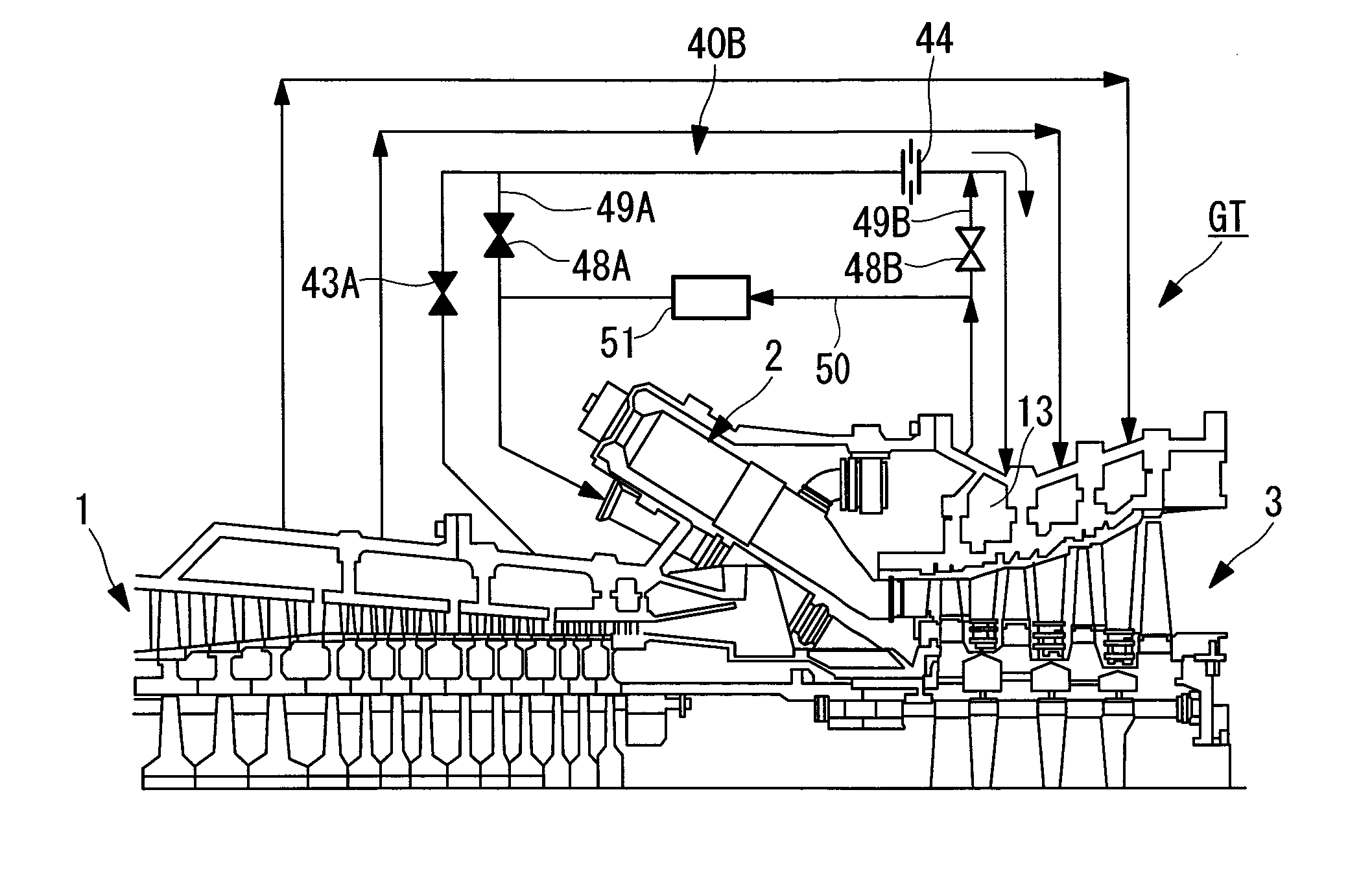
[0082]Next, a second embodiment of the gas turbine GT of the present invention will be described on the basis of FIGS. 4A and 4B. Note that parts the same as those in the above-described embodiment will be denoted by the same reference numerals, and detailed descriptions thereof will be omitted.

[0083]This embodiment is applied to the case where a cooling air system 40B of the second-stage turbine stator blades T2C has no cooler. The blade ring 12 is cooled by cooling air for the second-stage turbine stator blades T2C. The cooling air forms the cooling-air flow paths. Furthermore, in this cooling air system 40B, part of the high-temperature compressed air introduced from the outlet of the compressor 1 as the rotor cooling air is used as the cooling air during start-up. Thus, the cooling air system 40B and the introduction pipe 50 for high-temperature compressed air are connected by a pair of connecting tubes 49A and 49B.

[0084]One of the connecting tubes, 49A, connects the cooling air...


PUM


Abstract

Provided is a gas turbine plant that enables active clearance control for ensuring tip clearance of first-stage turbine rotor blades required during start-up and for achieving the minimum tip clearance during load operation. In a gas turbine plant including a cooler in an air system used for cooling second-stage turbine stator blades, a first-stage segmented ring and a second-stage segmented ring that oppose tips of first-stage turbine rotor blades and second-stage turbine rotor blades are supported by the same blade ring member, and a cooling-air for the second-stage turbine stator blades forms a cooling air flow cooling the blade ring, to control thermal expansion of the blade ring and to control the clearance with respect to the tips.

Description

RELATED APPLICATIONS[0001]The present application is a national phase PCT / JP2009 / 050772, filed Jan. 20, 2009.TECHNICAL FIELD[0002]The present invention relates to gas turbine plants in which tip clearance control of first-stage turbine rotor blades can be performed.BACKGROUND ART[0003]Tip clearance in a gas turbine varies depending on the expansion and contraction of rotation-side structural members and stationary-side structural members due to the difference between the temperature during start-up and that during rated operation, and by the centrifugal extension thereof due to the rotation. That is, the variation in the tip clearance is influenced by the temperature at the outlet of a compressor and the temperature of combustion gas, making the clearance of first-stage turbine rotor blades particularly tight.[0004]In a conventional structure, when there is no temperature adjusting means (for example, a steam path) on the stationary side of a turbine unit, the amount of thermal expa...

Claims


Application Information

Patent Timeline
IPC IPC(8): F01D5/08
CPCF01D11/24F05D2240/11F02C7/18F01D9/041F01D11/08F02C7/143F02C7/28F02C9/18
Inventor TAKAHASHI, TATSUJIHAGI, NAOKIAI, TOSHISHIGE
Owner MITSUBISHI HEAVY IND LTD
Why Eureka
Try Eureka