
Abradable coating and method for forming same

a technology of abradable coating and abradable material, which is applied in the direction of efficient propulsion technology, stators, machines/engines, etc., can solve the problems of insufficient monoclinic crystal structure of zirconia ceramic material, inability to achieve martensitic transformation easily, and use of high-temperature water treatment apparatus, etc., to achieve excellent cutting, improve gas turbine performance, and reduce the effect of tip clearan

Inactive Publication Date: 2004-02-05
HASEZAKI KAZUHIRO +2
View PDF6 Cites 27 Cited by
  • Summary
  • Abstract
  • Description
  • Claims
  • Application Information

AI Technical Summary

Benefits of technology

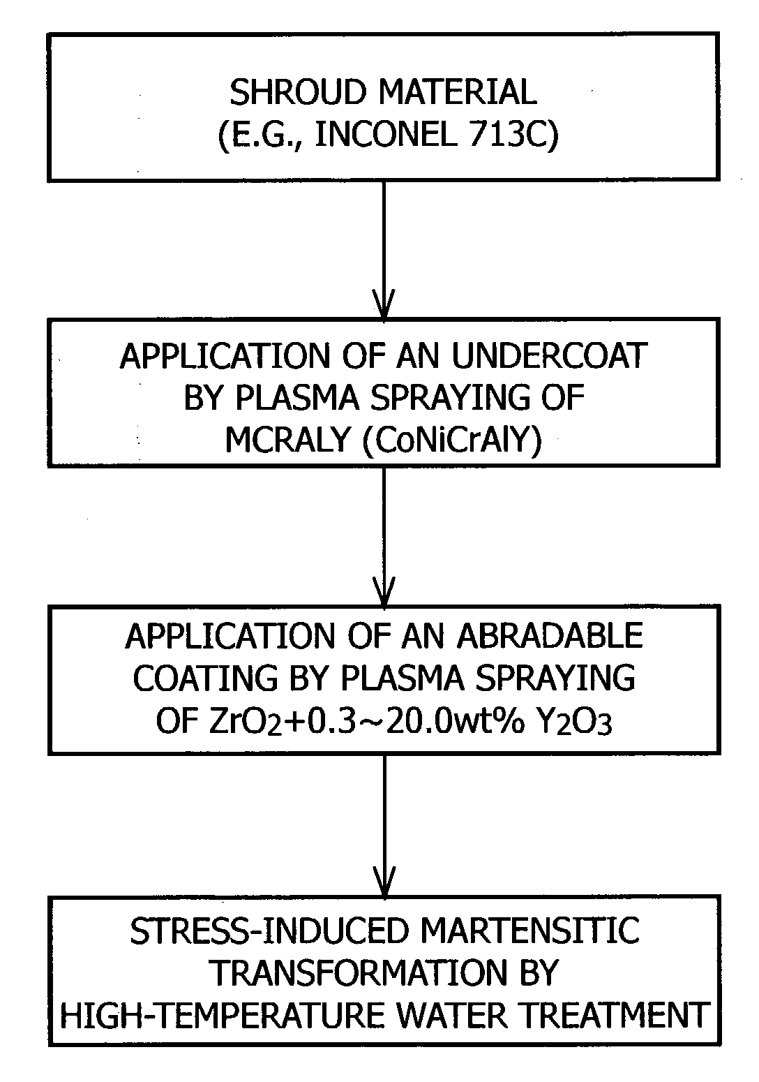
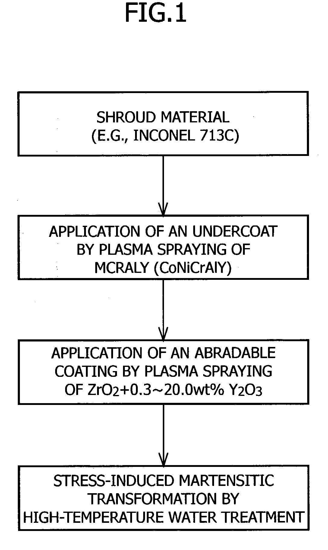
[0009] Usually, a zirconia ceramic material has a cubic or tetragonal crystal structure and is a hard material as evidenced by a Vickers hardness (Hv) of about 1,000. When this zirconia ceramic material is heat-treated in high-temperature water, stress-induced martensitic transformation occurs in the zirconia ceramic material owing to a high temperature applied thereto by water vapor, so that its crystal structure changes into a monoclinic crystal structure. This monoclinic zirconia ceramic material is soft as evidenced by a Vickers hardness (Hv) of about 800 or less, and has good cuttability. Accordingly, when this monoclinic zirconia ceramic material is applied to the shrouds of a gas turbine used in a high-temperature environment, it is soft and exhibits excellent cuttability at the time of a first operation (i.e., a test run) carried out to adjust the tip clearance between the blades and the shrouds. Moreover, when the zirconia ceramic material undergoes a thermal history by exposure to high temperatures (e.g., 1,000.degree. C. or above) resulting from gas turbine operation during the first operation, its crystal structure is transformed into a cubic or tetragonal crystal structure. Consequently, it increases in hardness and can maintain abrasion resistance during second and further operations.
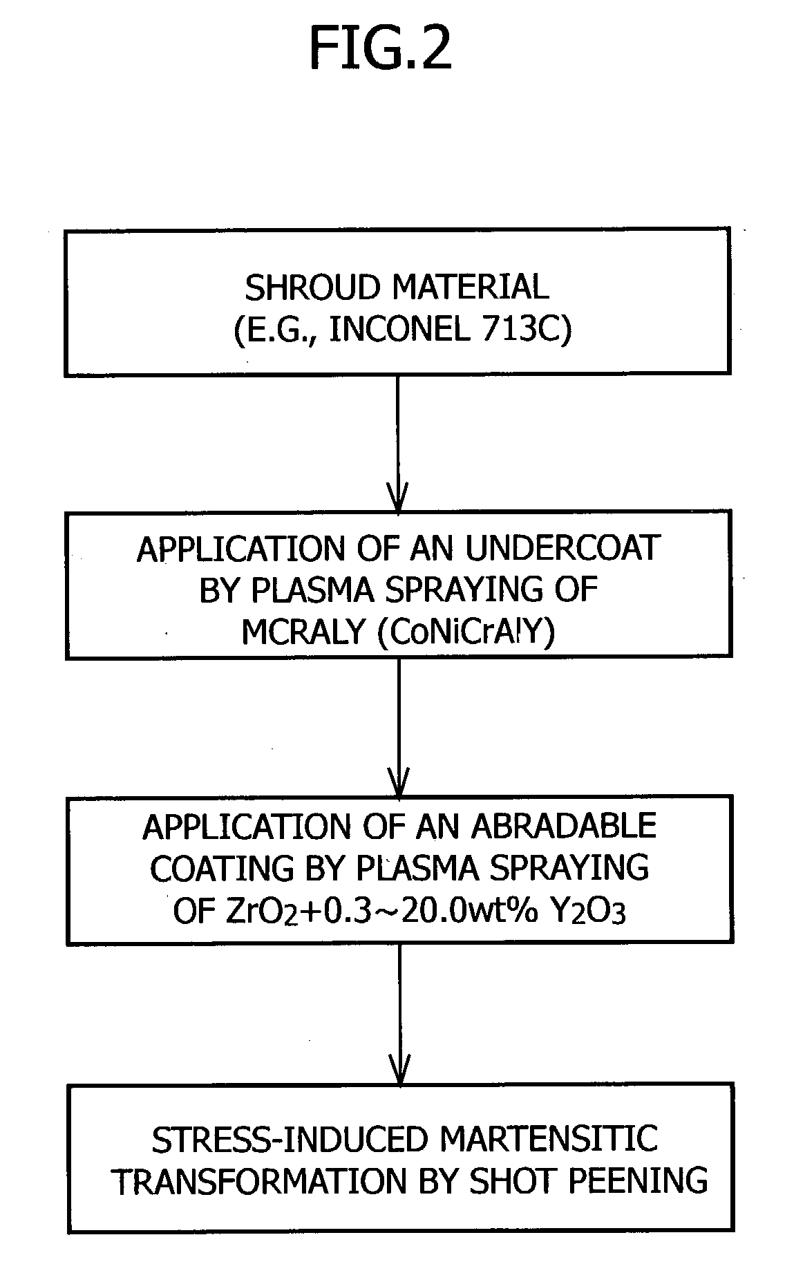
[0037] FIG. 2 is a flow chart illustrating a method for forming an abradable coating in accordance with a second embodiment. This method includes the step of subjecting the zirconia ceramic layer to shot peening and thereby causing it to undergo stress-induced martensitic transformation and produce an abradable coating having excellent cuttability.

Problems solved by technology

If the temperature of the high-temperature water is lower than 100.degree. C. or the treating time is less than 1 hour, stress-induced martensitic transformation will not occur easily and the zirconia ceramic material cannot be sufficiently transformed into a monoclinic crystal structure.
On the other hand, if the temperature of the high-temperature water is higher than 450.degree. C., the use of the high-temperature water treatment apparatus will be limited, and if the treating time is greater than 300 hours, the coating treatment will require too much time and cost for practical purposes.

Method used


Image

  • Abradable coating and method for forming same
  • Abradable coating and method for forming same
  • Abradable coating and method for forming same

Examples


example 1

[0043] As illustrated in FIG. 1, Inconel 713C was used as the shroud material. First of all, in order to relax the differential thermal expansion between the shroud material and a zirconia ceramic layer as will be described later, an undercoat was applied to the shroud material by plasma-spraying CoNiCrAlY to a thickness of 100 to 250 .mu.m. This plasma spraying was carried out in air at an electric current of about 500 to 600 A. As the working gas, there was used a gaseous mixture composed of argon gas and hydrogen gas. The mixing ratio of argon gas and hydrogen gas was about 5:1, and the total flow rate thereof was in the range of 40 to 50 liters per minute. The distance between the plasma spraying torch and the shroud material was in the range of 100 to 150 mm, and the feed rate of powder was in the range of 30 to 40 g per minute. The plasma spraying was carried out by moving the spraying torch back and forth across Inconel 713C until it was coated with CoNiCrAlY to a thickness o...

example 2

[0049] As illustrated in FIG. 2, Inconel 713C was used as the shroud material. First of all, in order to relax the differential thermal expansion between the shroud material and a zirconia ceramic layer as will be described later, an undercoat was applied to the shroud material by plasma-spraying CoNiCrAlY in air to a thickness of 100 to 250 .mu.m. This plasma spraying was carried out by using an electric current of about 500 to 600 A and a working gas comprising a gaseous mixture composed of argon gas and hydrogen gas. The mixing ratio of argon gas and hydrogen gas was about 5:1, and the total flow rate thereof was in the range of 40 to 50 liters per minute. The distance between the plasma spraying torch and the shroud material was in the range of 100 to 150 mm, and the feed rate of powder was in the range of 30 to 40 g per minute. The plasma spraying was carried out by moving the spraying torch back and forth across the shroud material until it was coated to a thickness of 100 to ...


PUM

PropertyMeasurementUnit
temperatureaaaaaaaaaa
temperaturesaaaaaaaaaa
temperatureaaaaaaaaaa

Abstract

The present invention provides an abradable coating which is applied to the surfaces of stationary parts in rotary machinery such as gas turbines and does not cause damage or other trouble to the blades, as well as a method for forming the same. This method for forming an abradable coating comprises the steps of coating a shroud material with a partially stabilized zirconia ceramic material to form a zirconia ceramic layer having a cubic or tetragonal crystal structure on the surface of the shroud material; and subjecting the shroud material having the zirconia ceramic layer formed thereon to high-temperature water treatment at a temperature of 100 to 450° C. for 1 to 300 hours and thereby transforming the crystal structure of the zirconia ceramic layer into a monoclinic crystal structure. Alternatively, shot peening may be employed in place of the high-temperature water treatment.

Description

FIELD OF THE INVENTION AND RELATED ART STATEMENT[0001] This invention relates to an abradable coating applied to the surfaces of stationary parts in rotary machinery such as gas turbines, and a method for forming the same. More particularly, it relates to an abradable coating having excellent cuttability which is applied, for example, to the shrouds of gas turbines, and a method for forming the same.[0002] As illustrated in FIG. 3, a gas turbine 101 usually includes a stationary shroud 103 attached to a casing (not shown) and blades 105 disposed within shroud 103 and capable of rotating around an axis of rotation (C) in the direction of rotation (r) shown by an arrow. Moreover, a very small clearance D is provided between the outer peripheral edge 105a of each blade 105 and the inner circumferential surface 103a of shroud 103. In order to suppress the leakage of hot gas, such as hot gas at about 1,500.degree. C., through this clearance D and thereby improve the performance of gas tu...

Claims


Application Information

Patent Timeline
Patent Type & Authority Applications(United States)
IPC IPC(8): C23C4/10F01D9/04C23C4/11C23C4/18C23C26/00F01D11/08F02C7/00F02C7/28
CPCC23C4/105Y02T50/67C23C4/18C23C4/11Y02T50/60
Inventor HASEZAKI, KAZUHIROSHIMIZU, KUNIHIROSENDA, MAKOTO
Owner HASEZAKI KAZUHIRO
Learn More