Known techniques for producing crossbar circuits require a large area for the crossbar circuitry due to the components required to form the crossbar circuitry and the significant number of control lines required for routing control signals to those components, and also consume significant power.
Further, their complexity tends to grow rapidly with size, making many of the known techniques impractical for use with crossbar circuits required to interconnect a large number of source circuits with a large number of destination circuits.
However, such MUX-based crossbar circuits are relatively large in size, and have a large
power consumption.
Further, they typically require a considerable number of control lines in order to control the various multiplexers.
Such MUX-based designs are not typically scalable with an increase in the number of inputs and outputs to be supported, at least in part because it becomes increasingly difficult as the size increases to
route the necessary control signals to the various multiplexers.
Further, if the input data is multi-bit data routed over an input
bus, the routing of the data paths themselves becomes very complex.
However, such a design requires a large number of control lines to program the various flip-
flops in order to configure the crossbar circuit to perform the required routing.
All of these factors give rise to significant problems in
layout of the elements of the, crossbar circuit and the associated control lines, particularly as the crossbar circuit increases in size to accommodate more inputs and outputs.
Accordingly, this approach becomes complex and is not scalable.
A significant
disadvantage of this design is that it consumes large power due to the requirement for current sensing devices to be located on each output path.
Further, a large number of control signals need routing within the crossbar circuitry, and indeed those control signals will dominate the routing requirements as the crossbar circuit increases in size to accommodate more inputs and outputs.
Hence, again, this design is not readily scalable to larger designs of crossbar circuitry.
Further, a large number of control lines will be required to enable
programming of the various flash-
EEPROM cells, and a significant amount of time will be required to program those various flash-
EEPROM cells.
Any reconfiguration of the crossbar device will hence also take a significant time.
Accordingly, such a design of crossbar is complex, and will increase in complexity as more input devices and output devices need to be supported by the crossbar, due to the proliferation in control lines required.
Further, since the timing of the crossbar is not deterministic, this will make the crossbar design inappropriate for certain implementations.
In summary, it will be appreciated from the above discussions that existing crossbar designs typically involve complex routing of control signals, with that complexity rapidly increasing as the size of the crossbar increases.
Often the designs consume significant
power consumption and lack
scalability, due partly to the number of control lines required, and partly due to the need to increase the size of certain components provided within the crossbar as the size of the crossbar increases.
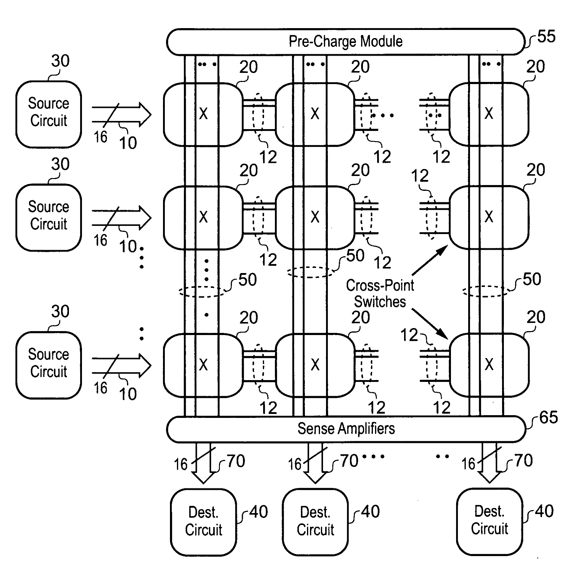
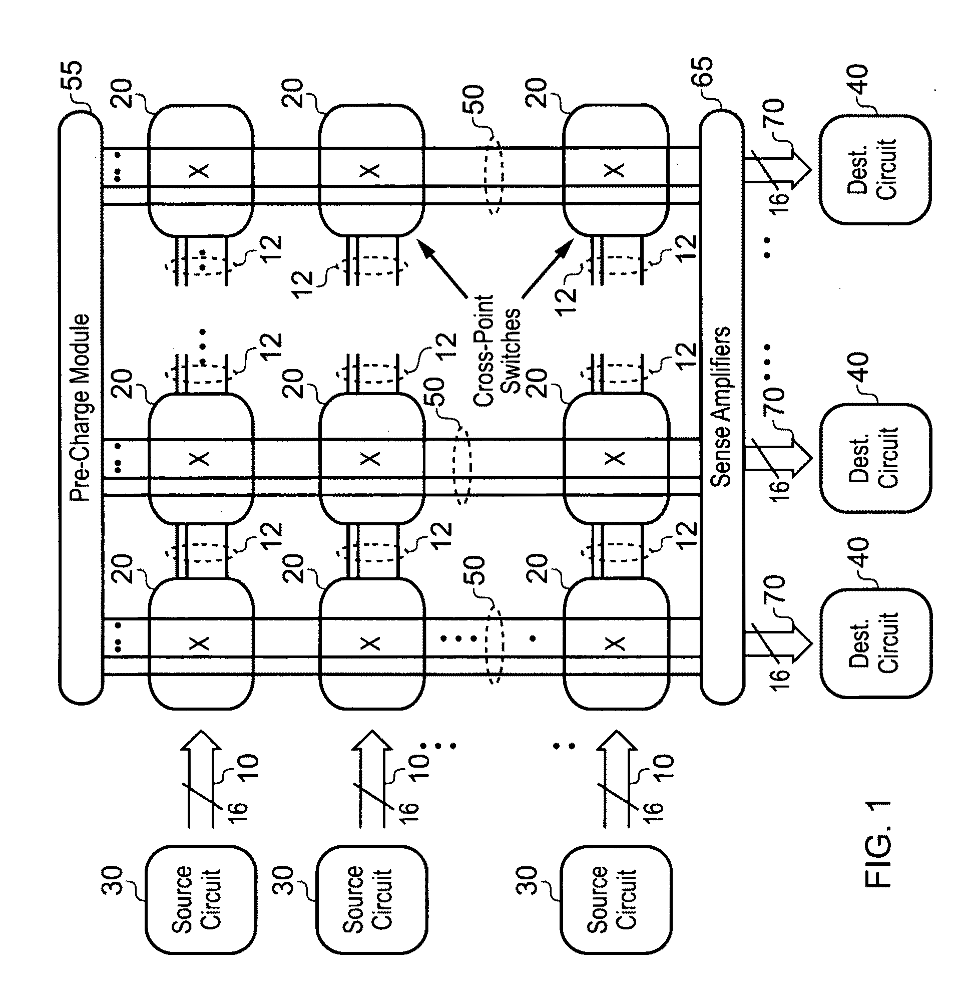
Another issue in crossbar design is how to provide the crossbar with
collision detection and resolution abilities.
With increasing number of sources and destinations, collisions get more frequent.
This scheme poses two major problems for
scalability:1) Routing all request signals from the source circuits to the
arbiter, and all the grant signals back, becomes increasingly difficult for larger systems; and2) The
arbiter needs to have knowledge of all incoming requests as well the current state of the crossbar, before it can make a decision.
This contributes to additional
delay.
However, the worst case arbitration
delay still remains the same.
sbar. However, the disclosed implementations are not scalable and are restricted to a crossbar of siz
However,
delay in meta-stable systems can become high at times, thereby restricting their use in real time systems that require guaranteed
throughput.
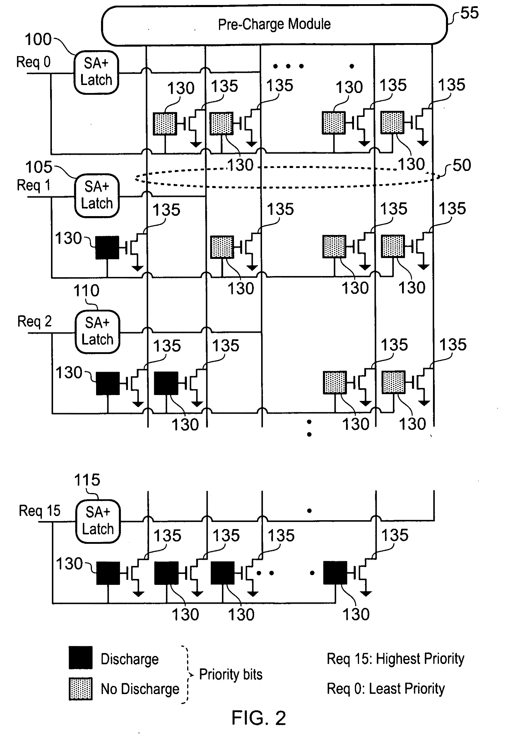
However, certain types of priority scheme are still difficult to implement efficiently, for example adaptive priority schemes where the relative priorities of the source circuits change between each application of the adaptive priority scheme.
However, such an approach impacts efficiency of the crossbar for a number of reasons.
Firstly it is necessary to enter a dedicated priority assignment mode of operation in order to reprogram the priority storage circuits, thereby causing
clock cycles to be spent purely performing the priority update process.
Furthermore, for the adaptive priority configuration module, it is necessary first to extract information from the crossbar indicative of the activities of the crossbar, then to analyse that extracted information, and then to input the revised priority data into the crossbar for storage within the relevant priority storage circuits, thereby leading to an inefficient update process.
Although the LRG priority scheme guarantees fairness, and a better
quality of service (QoS) than other priority schemes (for example round-robin, pseudo round-robin, random priority assignment, etc), its hardware implementation typically results in a significant overhead in the area, performance and
energy consumption of the crossbar circuit.

