Eureka AIR delivers breakthrough ideas for toughest innovation challenges, trusted by R&D personnel around the world.

Crossbar circuitry for applying an adaptive priority scheme and method of operation of such crossbar circuitry

a crossbar circuit and priority scheme technology, applied in the field of crossbar circuitry, can solve the problems of large consumption of power, large complexity of crossbar circuits, and many known techniques that are impractical, and achieve the effect of simple, scalable and power-efficient mechanisms

Active Publication Date: 2013-10-01
RGT UNIV OF MICHIGAN
View PDF54 Cites 7 Cited by
  • Summary
  • Abstract
  • Description
  • Claims
  • Application Information

AI Technical Summary

Benefits of technology

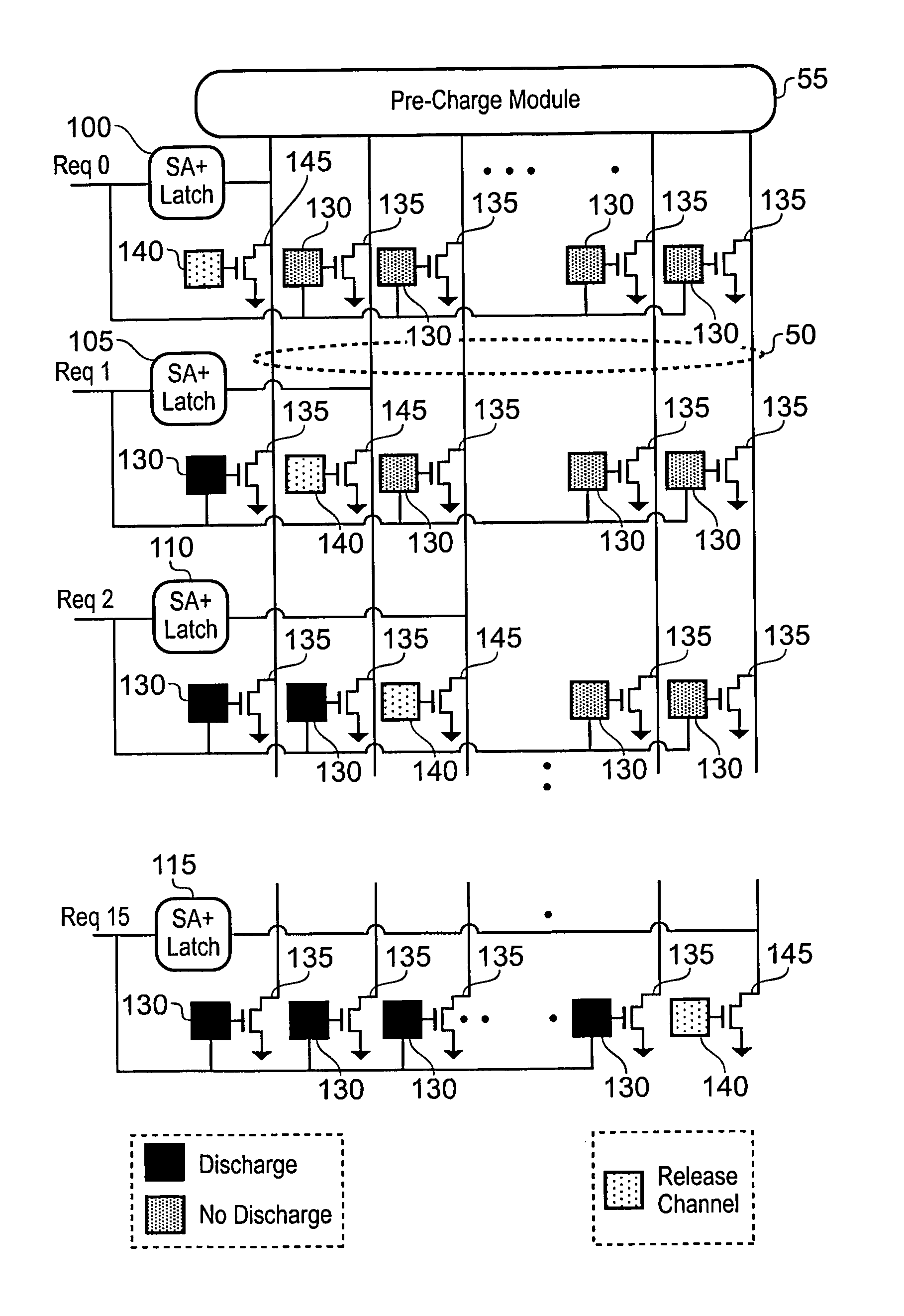
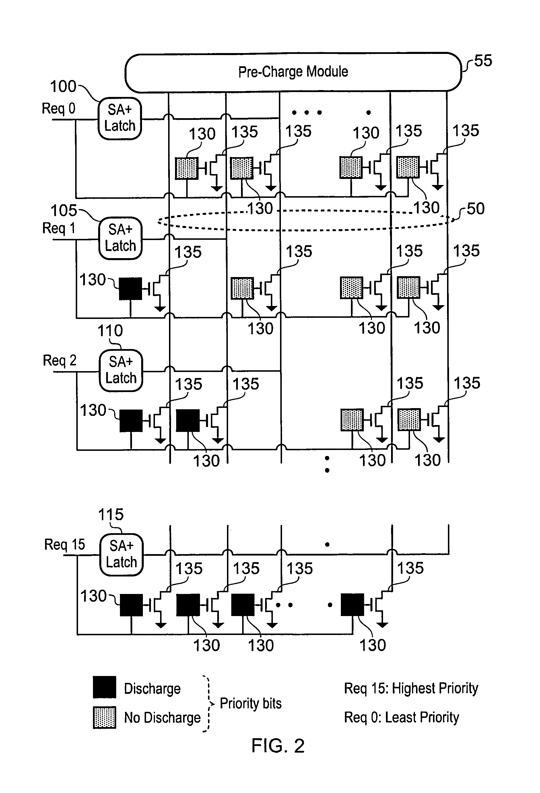
[0035]Hence, it can be seen that in accordance with the present invention, in the arbitration mode of operation, the bit lines of the data output paths are re-used to detect conflicts for particular data output paths, to resolve those conflicts such that at any point in time only one source circuit is granted access to a particular data output path, and to update the priority data stored in the priority storage circuitry. This provides a fast and scalable technique for implementing adaptive priority schemes within a crossbar circuit. The approach is significantly more scalable than prior art techniques (in embodiments of the present invention the hardware complexity grows linearly with the size of the interconnection network provided by the crossbar), and can be implemented with little overhead to the interconnection network, and little performance impact.
[0076]The crossbar circuitry of embodiments of the present invention provides a particularly simple, scalable and power efficient mechanism for routing data values from any of the memory devices to any of the processors.

Problems solved by technology

Known techniques for producing crossbar circuits require a large area for the crossbar circuitry due to the components required to form the crossbar circuitry and the significant number of control lines required for routing control signals to those components, and also consume significant power.
Further, their complexity tends to grow rapidly with size, making many of the known techniques impractical for use with crossbar circuits required to interconnect a large number of source circuits with a large number of destination circuits.
However, such MUX-based crossbar circuits are relatively large in size, and have a large power consumption.
Further, they typically require a considerable number of control lines in order to control the various multiplexers.
Such MUX-based designs are not typically scalable with an increase in the number of inputs and outputs to be supported, at least in part because it becomes increasingly difficult as the size increases to route the necessary control signals to the various multiplexers.
Further, if the input data is multi-bit data routed over an input bus, the routing of the data paths themselves becomes very complex.
However, such a design requires a large number of control lines to program the various flip-flops in order to configure the crossbar circuit to perform the required routing.
All of these factors give rise to significant problems in layout of the elements of the crossbar circuit and the associated control lines, particularly as the crossbar circuit increases in size to accommodate more inputs and outputs.
Accordingly, this approach becomes complex and is not scalable.
A significant disadvantage of this design is that it consumes large power due to the requirement for current sensing devices to be located on each output path.
Further, a large number of control signals need routing within the crossbar circuitry, and indeed those control signals will dominate the routing requirements as the crossbar circuit increases in size to accommodate more inputs and outputs.
Hence, again, this design is not readily scalable to larger designs of crossbar circuitry.
Further, a large number of control lines will be required to enable programming of the various flash-EEPROM cells, and a significant amount of time will be required to program those various flash-EEPROM cells.
Any reconfiguration of the crossbar device will hence also take a significant time.
Accordingly, such a design of crossbar is complex, and will increase in complexity as more input devices and output devices need to be supported by the crossbar, due to the proliferation in control lines required.
Further, since the timing of the crossbar is not deterministic, this will make the crossbar design inappropriate for certain implementations.
In summary, it will be appreciated from the above discussions that existing crossbar designs typically involve complex routing of control signals, with that complexity rapidly increasing as the size of the crossbar increases.
Often the designs consume significant power consumption and lack scalability, due partly to the number of control lines required, and partly due to the need to increase the size of certain components provided within the crossbar as the size of the crossbar increases.
Another issue in crossbar design is how to provide the crossbar with collision detection and resolution abilities.
With increasing number of sources and destinations, collisions get more frequent.
This scheme poses two major problems for scalability:1) Routing all request signals from the source circuits to the arbiter, and all the grant signals back, becomes increasingly difficult for larger systems; and2) The arbiter needs to have knowledge of all incoming requests as well the current state of the crossbar, before it can make a decision.
This contributes to additional delay.
However, the worst case arbitration delay still remains the same.
bar. However, the disclosed implementations are not scalable and are restricted to a crossbar of size
However, delay in meta-stable systems can become high at times, thereby restricting their use in real time systems that require guaranteed throughput.
Hence, the delay grows linearly with the size of the crossbar switch.
However, certain types of priority scheme are still difficult to implement efficiently, for example adaptive priority schemes where the relative priorities of the source circuits change between each application of the adaptive priority scheme.
However, such an approach impacts efficiency of the crossbar for a number of reasons.
Firstly it is necessary to enter a dedicated priority assignment mode of operation in order to reprogram the priority storage circuits, thereby causing clock cycles to be spent purely performing the priority update process.
Furthermore, for the adaptive priority configuration module, it is necessary first to extract information from the crossbar indicative of the activities of the crossbar, then to analyse that extracted information, and then to input the revised priority data into the crossbar for storage within the relevant priority storage circuits, thereby leading to an inefficient update process.

Method used


Image

  • Crossbar circuitry for applying an adaptive priority scheme and method of operation of such crossbar circuitry
  • Crossbar circuitry for applying an adaptive priority scheme and method of operation of such crossbar circuitry
  • Crossbar circuitry for applying an adaptive priority scheme and method of operation of such crossbar circuitry

Examples


Embodiment Construction

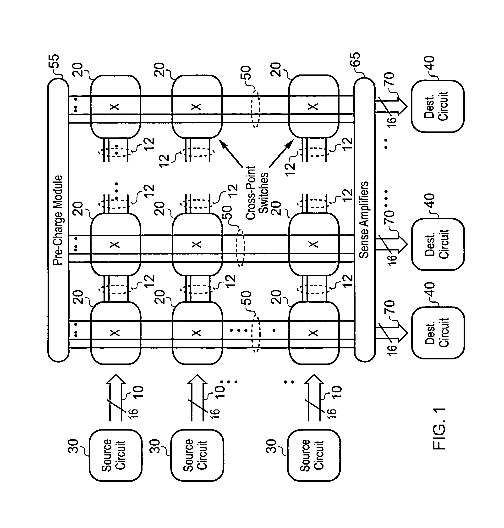
[0098]FIG. 1 illustrates a top-level diagram of a proposed switching fabric, comprising a crossbar circuitry in accordance with one embodiment and a plurality of source circuits and destination circuits connected thereto. The crossbar circuitry includes a plurality of data input paths 12 running in a first direction through the crossbar circuitry, and a plurality of data output paths 50 running in a second direction transverse to the first direction. In the embodiment of FIG. 1, both of these paths are formed by multi-bit buses, and in particular each data input path comprises a plurality of word lines and each data output path comprises a plurality of bit lines.

[0099]At the intersection between each data input path and data output path, a crossbar cell 20 is provided, which is used to selectively route data received on the associated data input path out on the associated data output path. Each crossbar cell includes a configuration storage element for storing the on / off status of e...


PUM


Abstract

Crossbar circuitry has an array of data input and output paths where the data output paths are transverse to the data input paths. At each intersection between a data input path and a data output path, a crossbar cell is provided which includes a configuration storage circuit programmable to store a routing value, a transmission circuit, and an arbitration circuit. In a transmission mode of operation, the transmission circuit is responsive to the routing value being a first value, indicating that the data input path should be coupled to the data output path, to detect the data input along the data input path, and to output an indication of that data on the data output path at the associated intersection. In an arbitration mode of operation, the arbitration circuitry is operable to selectively modify the voltage on said plurality of bit lines in order to apply an adaptive priority scheme.

Description

[0001]This application is a continuation-in-part of U.S. application Ser. No. 12 / 458,511 filed Jul. 14, 2009 now U.S. Pat. No. 8,230,152, which is a continuation-in-part of U.S. application Ser. No. 12 / 379,191 filed Feb. 13, 2009 now U.S. Pat. No. 8,108,585, the entire contents of each of which are hereby incorporated by reference.BACKGROUND OF THE INVENTION[0002]1. Field of the Invention[0003]The present invention relates to crossbar circuitry for applying an adaptive priority scheme, and a method of operation of such crossbar circuitry.[0004]2. Description of the Prior Art[0005]A crossbar circuit is a switch infrastructure for connecting multiple inputs to multiple outputs in a matrix manner. Accordingly, crossbar circuitry can be used to interconnect a plurality of source circuits and a plurality of destination circuits such that data input to the crossbar circuitry from any of the plurality of source circuits can be output to any of the plurality of destination circuits. Crossba...

Claims


Application Information

Patent Timeline
Patent Type & Authority Patents(United States)
IPC IPC(8): G06F13/00H04Q11/00H04Q3/00H03K17/00G06F9/32G11C19/00H04L12/50
CPCG11C7/10H03K17/693
Inventor SATPATHY, SUDHIR KUMARBLAAUW, DAVID THEODOREMUDGE, TREVOR NIGELSYLVESTER, DENNIS MICHAEL
Owner RGT UNIV OF MICHIGAN
Why Eureka
Eureka Blog
Learn More