
Piston for an internal combustion engine

a technology for internal combustion engines and pistons, which is applied to trunk pistons, machines/engines, and plungers, etc., can solve the problems of resin coatings that are easily worn out and/or peeling off, and the surface pressure which the skirt receives from the inner wall of the cylinder is by no means uniform, so as to reduce the diameter, improve the frictional property, and reduce the effect of wear and other damage to the resin coating layer

Active Publication Date: 2011-06-16
HONDA MOTOR CO LTD
View PDF7 Cites 38 Cited by
  • Summary
  • Abstract
  • Description
  • Claims
  • Application Information

AI Technical Summary

Benefits of technology

[0005]However, the surface pressure which the skirt receives from the inner wall of the cylinder is by no means even. Such a non-uniformity in the surface pressure is caused by the behavior of the piston as it reciprocates and the structure of the piston. When a resin coating layer is formed in a part where a high surface pressure is expected, the resin coating tends to be wear out and / or peel off. Also, the lubricating oil is highly effective reducing the frictional resistance. Therefore, depending on the layout of the resin coating and pits, the frictional property and the durability of the resin coating may vary significantly.
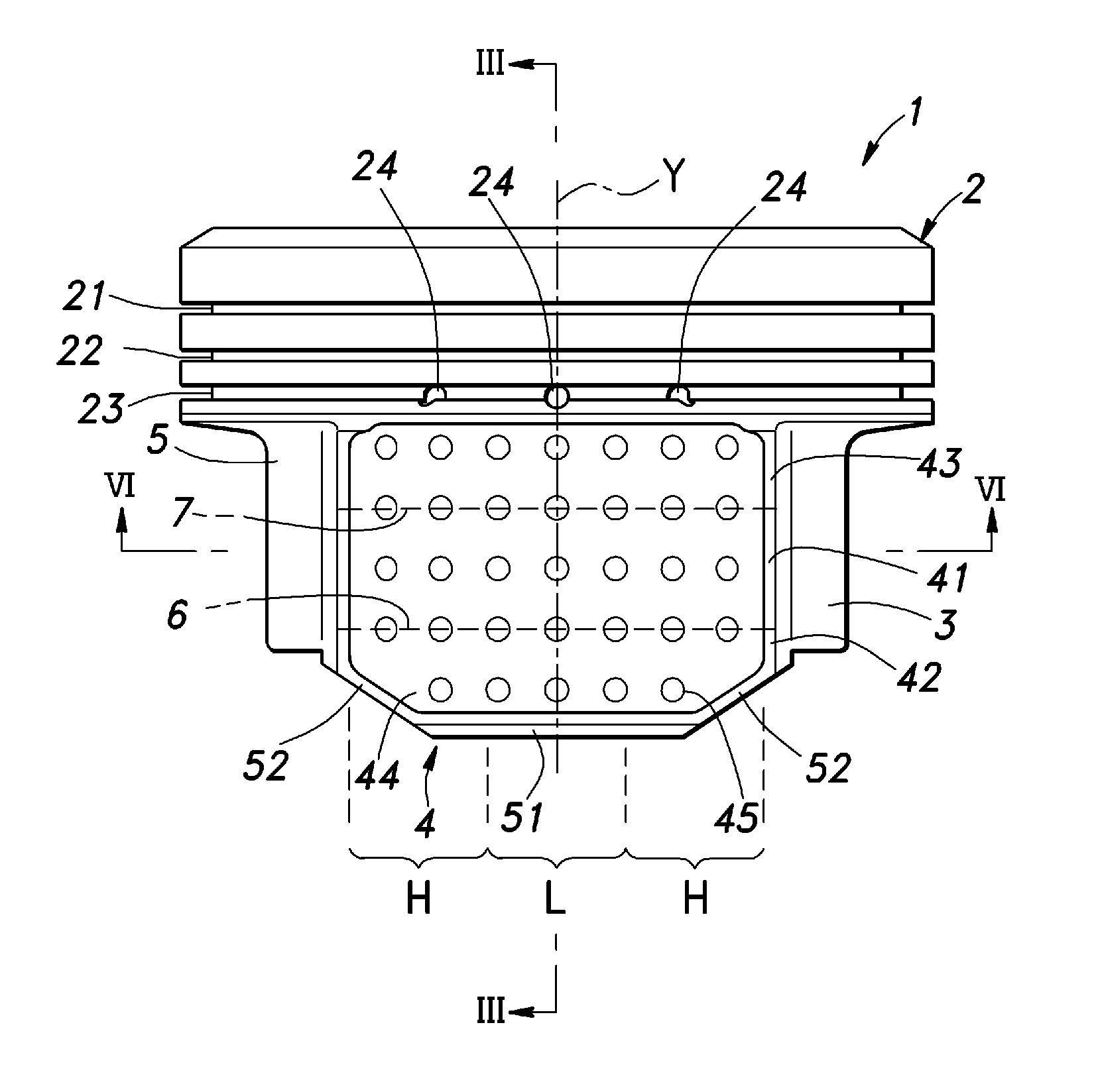
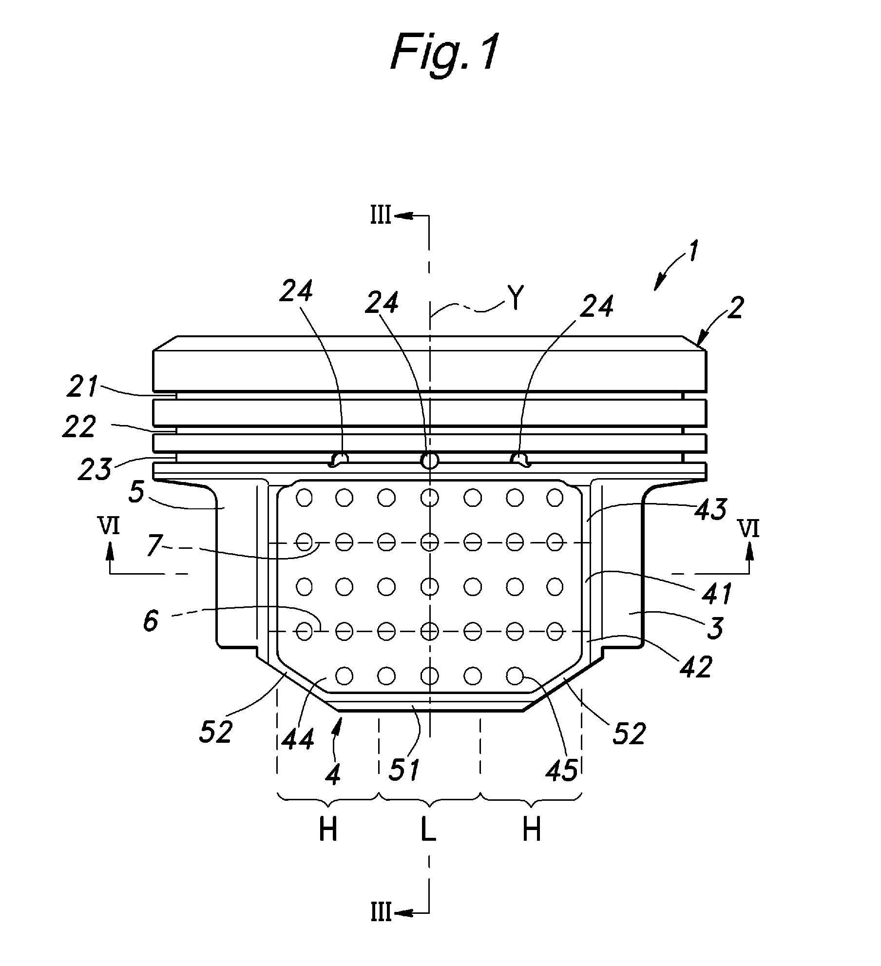
[0009]Thus, the dimples serving as reservoir for lubricating oil are arranged in the thick walled portion that is subjected to the highest surface pressure during the reciprocating movement of the piston. The lubrication by the lubricating oil is more effective in reducing friction than that by the resin coating so that the overall lubricating property can be improved. In particular, because any break in the oil film between the resin coating layer and cylinder inner wall in the area where the surface pressure is relatively high can be avoided, and this reduces the wear and other damages to the resin coating layer.
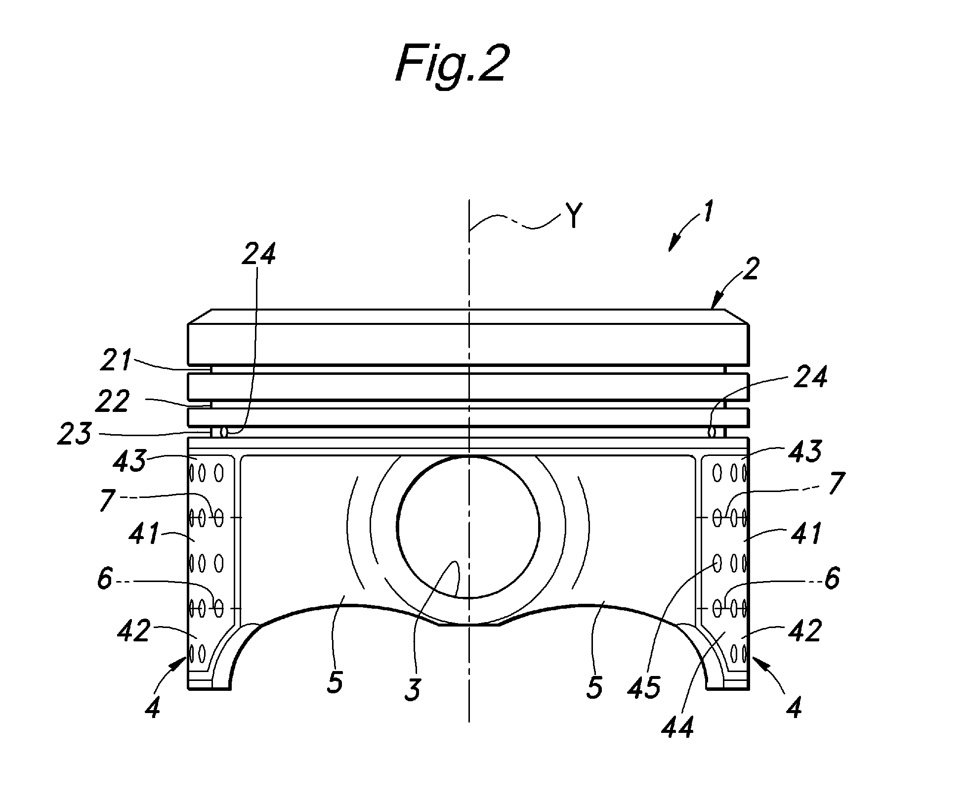
[0010]Preferably, the head comprises an annular oil ring groove around a circumference thereof and an oil ejection hole communicating a bottom part of the oil ring groove with an interior of the piston, and the oil ejection holes are provided adjacent to the dimples. Because a relatively large amount of lubricating oil can be retained in the dimples of the thick walled portion, by providing the oil ejection hole so as to axially align with one of the dimples in the thick walled portion, excess lubricating oil can be efficiently removed from this part during the reciprocating movement of the piston, and an appropriate amount of lubricating oil can be maintained in this part.
[0014]Thereby, the skirt is given with a barrel shape with the skirt main body protruding radially as compared with the remaining part thereof. As the piston having such a skirt reciprocates in a cylinder, the first and second boundaries and lower part of the skirt are pressed more forcibly against the cylinder inner wall than other parts of the skirt. By providing the dimples in the parts which are relatively forcibly pressed against the cylinder inner wall, an adequate amount of lubricating oil can be supplied to such parts, and the frictional property can be improved. Also, the direct contact between the resin coating layer deposited on the skirt and the cylinder inner wall, and the wear and other damages to the resin coating layer can be minimized.
[0015]Preferably, the dimples include those arranged in parallel with the first boundary between the first and second reduced diameter portions. By thus providing the dimples between the first and second reduced diameter portions, the lubricating oil retained by these dimples can be supplied to the parts adjacent to the first and second boundaries so that the shortage of lubricating oil in the parts adjacent to the first and second boundaries can be avoided.
[0016]Preferably, the head comprises an annular oil ring groove around a circumference thereof and an oil ejection hole communicating a bottom part of the oil ring groove with an interior of the piston, the oil ejection hole being located so as to axially align with one of the dimples. Because lubricating oil can be particularly favorably retained in the skirt where the dimples are formed, excess lubricating oil can be efficiently removed by providing the oil rejection hole in the axial direction as seen from the dimple, and an appropriate amount of lubricating oil can be maintained.

Problems solved by technology

However, the surface pressure which the skirt receives from the inner wall of the cylinder is by no means even.
Such a non-uniformity in the surface pressure is caused by the behavior of the piston as it reciprocates and the structure of the piston.
When a resin coating layer is formed in a part where a high surface pressure is expected, the resin coating tends to be wear out and / or peel off.

Method used


Image

  • Piston for an internal combustion engine
  • Piston for an internal combustion engine
  • Piston for an internal combustion engine

Examples


Embodiment Construction

)

[0024]Now the present invention is described in the following in more detail in terms of a concrete embodiment with reference to the appended drawings. In the following disclosure, it is assumed that the head of the piston is directed upward.

[0025]As shown in FIGS. 1 and 2, the piston 1 comprises a head 2 for partly defining a combustion chamber in the cylinder of the internal combustion engine, a pair of piston pin bore defining walls 5 depending from diametrically opposing parts of the head 2 and defining a pair of piston pin bores 3 for receiving a piston pin and a pair of skirts 4 depending from diametrically opposing parts of the head 2 in an alternating relationship to the piston pin bore defining walls 5 for slidable engagement with the inner wall of the cylinder. The piston pin bore defining walls 5 extend circumferentially so as to connect the skirts 4 with each other.

[0026]As shown in FIG. 3, the head 2 is given with an inverted cup-shape. The upper face of the head 2 is ...


PUM


Abstract

To provide a piston for an internal combustion engine including a skirt which causes a relatively small frictional resistance and can maintain a favorable frictional property over an extended period of time. In a piston for an internal combustion engine having a skirt 4 on whose sliding surface a resin coating layer is deposited, the skirt 4 comprises a thin walled portion 51 located in a circumferentially middle part thereof and a pair of thick walled portions 52 provided on either lateral side of the thin walled portion 51. The resin coating layer 44 at least in the part thereof deposited on the thick walled portions 52 is formed with a plurality of dimples 45. The skirt may comprise a skirt main body 41 extending axially at a fixed distance from the central axial line of the piston in an axially middle part thereof, and a first reduced diameter portion 42 depending from the lower end of the skirt main body and having a progressively smaller diameter toward a lower end thereof. The dimples 45 may be arranged along a first boundary 6 between the skirt main body and first reduced diameter portion.

Description

TECHNICAL FIELD[0001]The present invention relates to a piston for an internal combustion engine including a skirt having a resin coating layer deposited thereof for reducing frictional resistance.BACKGROUND OF THE INVENTION[0002]A skirt of a piston controls the tilting movement of the piston which is caused during a reciprocating movement of the piston by slidably engaging the inner wall of the cylinder. Therefore, if the frictional resistance acting on the surface of the skirt is excessive, the frictional load opposing the reciprocating movement of the piston increases, and this could cause a reduction in fuel economy and an excessive wear.[0003]Therefore, it has been proposed to improve the frictional property by depositing a resin coating layer impregnated with solid lubricant on the surface of the skirt, and to form small recesses in the skirt so as to retain lubricating oil in each recess. However, a resin coating layer wears out in time, and a desired frictional property of t...

Claims


Application Information

Patent Timeline
Patent Type & Authority Applications(United States)
IPC IPC(8): F02F3/10
CPCF02F3/027F16J1/04F02F3/105
Inventor NAKAZAWA, FUMIKAZUTANIHATA, AKITOSATO, NAOKOYOSHIZAWA, JUNYA
Owner HONDA MOTOR CO LTD
Learn More