Method for the production and removal of a temporary protective layer for a cathodic coating

Active Publication Date: 2011-06-16
VOESTALPINE STAHL GMBH
View PDF4 Cites 10 Cited by
  • Summary
  • Abstract
  • Description
  • Claims
  • Application Information

AI Technical Summary

Benefits of technology

[0018]“Pretreatment” is understood here to mean a preoxidation of the blank steel band as described in DE 100 59 566 B3 and in EU Search Report No. 7210-PA/118. This type of pretreatment is conventionally used to optimize the properties of high-strength steels. This improves the adhesion properties of the zinc coating in the hot-dip coating process, particularly with steel bands containing high levels of alloy constituents.
[0019]As a result, the inhibiting layer formation can affect the thickness and cracking of the fine protective layer. An “inhibiting layer” refers to a layer that, due to an addition of aluminum to the zinc bath, forms between the steel substrate and the zinc layer during the continuous hot-dip coating process and the possibly subseque

Problems solved by technology

On the other hand, there is no alternative to the formation of these thin layers since otherwise, the only possib

Method used


Image

  • Method for the production and removal of a temporary protective layer for a cathodic coating
  • Method for the production and removal of a temporary protective layer for a cathodic coating
  • Method for the production and removal of a temporary protective layer for a cathodic coating

Examples


example 1

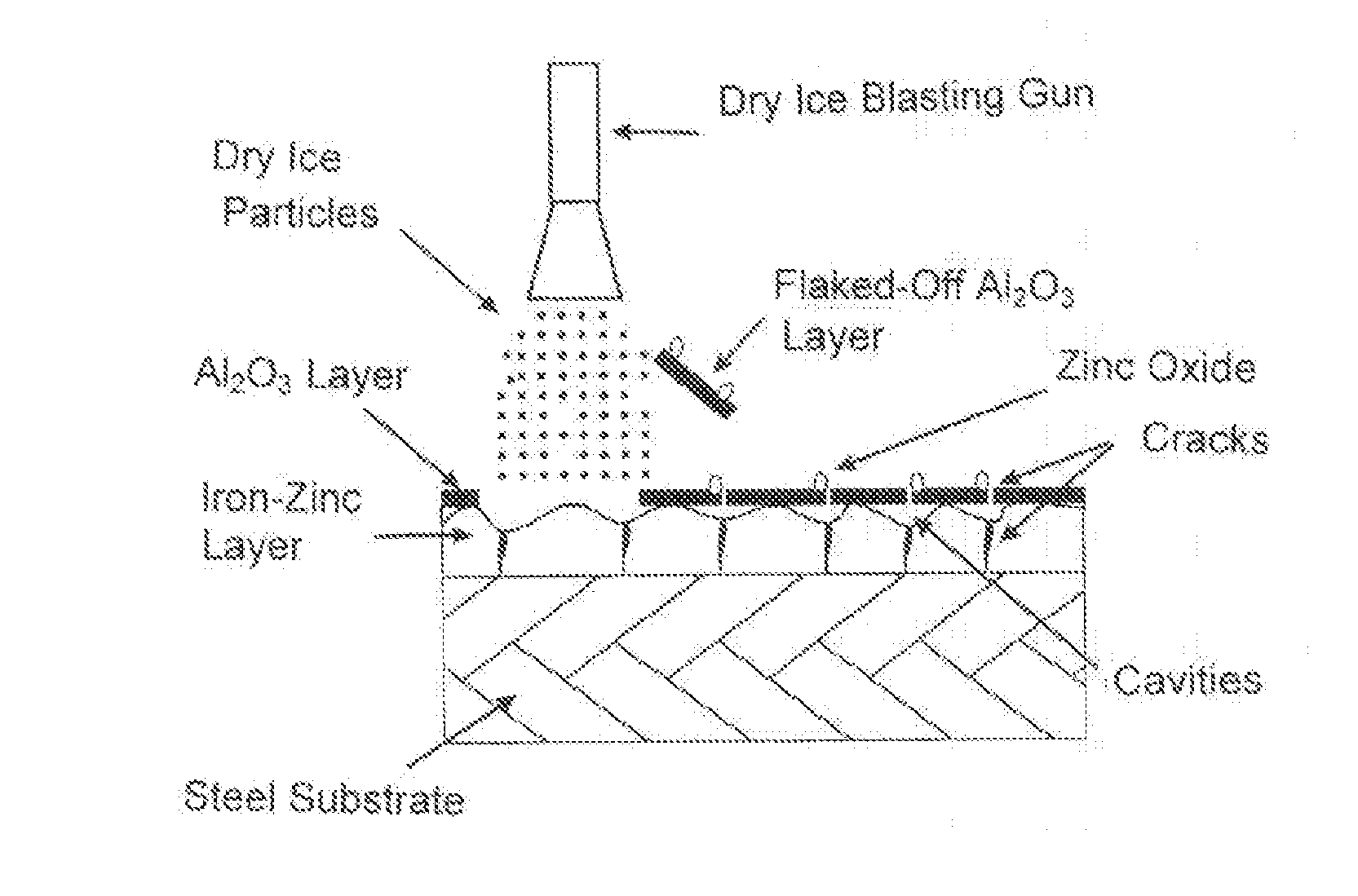
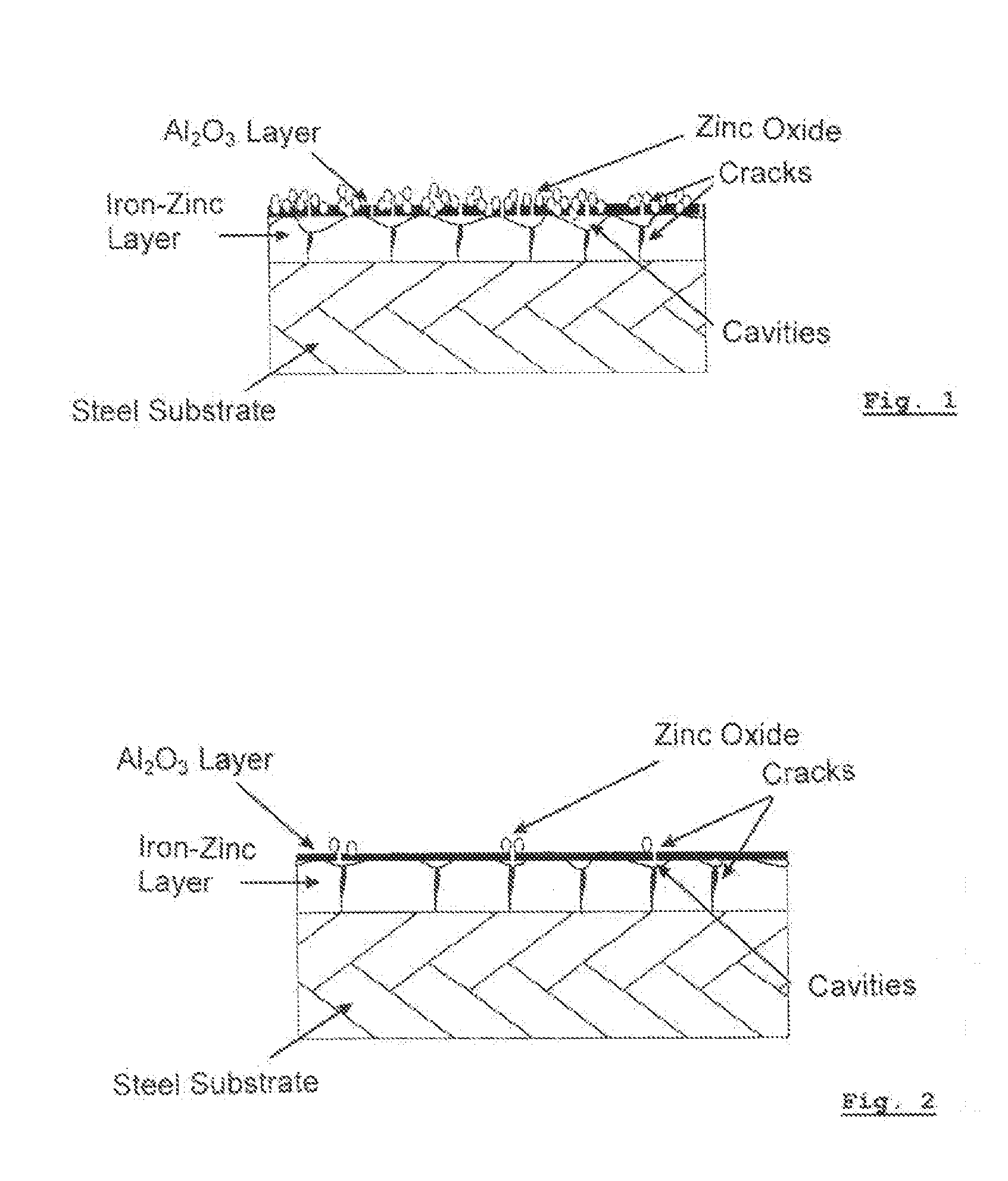
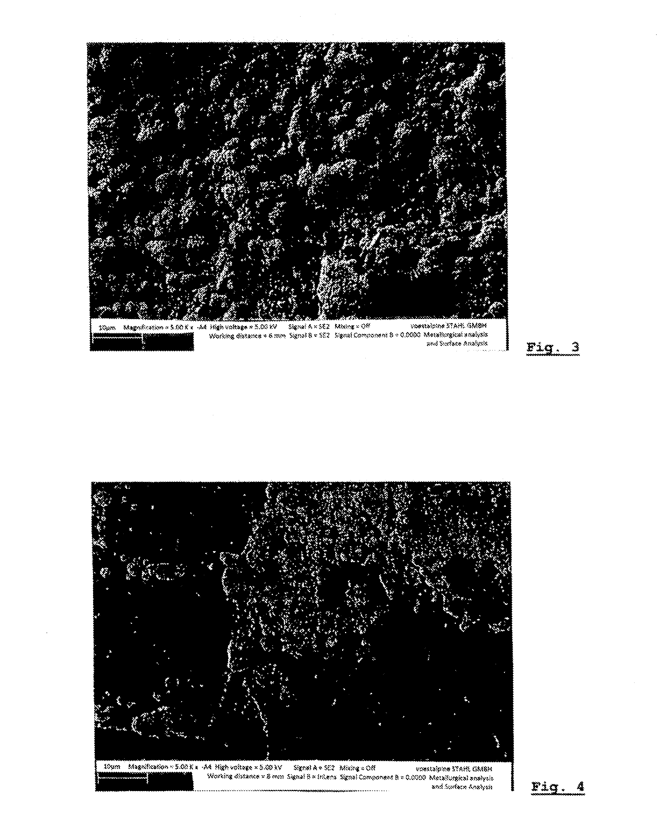
[0039]A sheet of 22MnB5 steel 1.0 mm thick is subjected to a preoxidation and a hot-dip coating with approx. 0.2 wt. % aluminum in a zinc bath. The preoxidation is carried out so that a FeO layer thickness of greater than 100 nm but less than 1,000 nm is produced. The galvanizing here is carried out so that a zinc deposit Z200, i.e. 14 μm per side, is achieved. The aluminum content of the inhibiting layer is set to 0.3 g / m2. The sheet is then placed for four minutes in a radiation furnace heated to 910° C., with a normal air atmosphere. As a result, a layer formation according to FIGS. 3 and 5 or according to FIG. 1 occurs. This layer responds favorably to cleaning with dry ice and yields the surface according to FIG. 5 and in subsequent trials, demonstrates the correspondingly favorable paint adhesion.

example 2

[0040]A sheet of 22MnB5 steel 1.0 mm thick undergoes a preoxidation and a hot-dip coating process with approx. 0.2 wt. % aluminum in the zinc bath. The preoxidation of the blank sheet is carried out so that a FeO layer thickness of greater than 100 nm and less than 1,000 nm is produced. The galvanizing here is carried out so that a zinc deposit Z200, i.e. 14 μm per side, is achieved. The aluminum content of the inhibiting layer is set to 0.8 g / m2 and annealing conditions correspond to example 1. As a result, an aluminum oxide-rich surface with little zinc oxide is achieved, which only responds poorly to being cleaned with dry ice. As a result, the surface corresponds to FIG. 6 or before the cleaning, to FIG. 4, and in subsequent trials, demonstrates the poor paint adhesion due to extensive Al2O3 coverage.

example 3

[0041]A steel sheet corresponding to examples 1 and 2 is embodied with a zinc deposit of Z300, i.e. 21 μm per side, instead of a zinc deposit of Z200. On the other hand, the preoxidation of the blank steel band is carried out so that a FeO layer thickness of greater than 100 nm and less than 1,000 nm is produced. The aluminum content of the inhibiting layer is set to 0.3 g / m2. The sheet is then placed for four minutes in a radiation furnace heated to 910° C., with a normal air atmosphere. Here, too, the Al2O3-rich surface not according to the invention forms with little zinc oxide; it responds poorly to being cleaned with dry ice and corresponds to the surface shown in FIG. 4. In subsequent paint trials, a poor paint adhesion is likewise achieved.

[0042]The invention has the advantage that a method for producing and removing a temporary protective layer for a cathodic coating is created, which successfully creates a hardened steel component with a cathodic protection; the cathodic pr...


PUM

PropertyMeasurementUnit
Lengthaaaaaaaaaa
Lengthaaaaaaaaaa
Nanoscale particle sizeaaaaaaaaaa

Abstract

The invention relates to a method for the production and removal of a temporary protective layer for a cathodic coating, particularly for the production of a hardened steel component with an easily paintable surface, wherein a steel sheet made of a hardenable steel alloy is subjected to a preoxidation, wherein said preoxidation forms a FeO layer with a thickness of 100 nm to 1,000 nm and subsequently a melt dip coating is conducted, wherein, during the melt dip coating, a zinc layer is applied having a thickness of 5 to 20 μm, preferably 7 to 14 μm, on each side, wherein the melt dip process and the aluminum content of the zinc bath is adjusted such that, during the melt dip coating, an aluminum content for the barrier layer results of 0.15 g/m2 to 0.8 g/m2 and the steel sheet or sheet components made therefrom is subsequently heated to a temperature above the austenitizing temperature and is then cooled at a speed greater than the critical hardening speed in order to cause hardening, wherein oxygen-affine elements are contained in the zinc bath for the melt dip coating in a concentration of 0.10 wt.-% to 15 wt.-% that, during the austenitizing on the surface of the cathodic protective layer, form a thin skin comprised of the oxide of the oxygen-affine elements and said oxide layer is blasted after hardening by irradiation of the sheet component with dry ice particles.

Description

FIELD OF THE INVENTION[0001]The invention relates to a method for producing and removing a temporary protective layer for a cathodic coating on supporting metals.BACKGROUND OF THE INVENTION[0002]EP 1 561 542 A1 has disclosed a method for removing a layer of a component. It involves a layer composed of an organic binding agent, which is to be removed from a substrate without damaging the substrate. To this end, a blasting jet of dry ice particles is guided over the surface so that the action of the dry ice particles removes material from the layer containing an organic binding agent. The dry ice removal is intended to avoid a contamination with foreign substances and to not harm the metallic base body of the component.[0003]EP 1 321 625 B1 has disclosed a method for removing a metal layer in which a layer system includes the metal layer and a substrate coated by the metal layer and in which the removal process is a blasting process. The blasting process here can be a sand blasting pr...

Claims


Application Information

Patent Timeline
IPC IPC(8): C23C8/10
CPCB24C1/086C21D1/68C21D8/0484C23C2/28C23C2/06C23C2/26C23C2/02B24C1/003B24C1/00
Inventor PERUZZI, MARTINFADERL, JOSEFKOLNBERGER, SIEGFRIEDBRANDSTATTER, WERNER
Owner VOESTALPINE STAHL GMBH
Why Eureka
Try Eureka