Fuel injector

a fuel injector and injector technology, applied in the direction of fuel injection apparatus, fluid pressure injection control, feed system, etc., can solve the problems of higher cost, two parts of the injection valve element do not exist,

Inactive Publication Date: 2011-06-16
ROBERT BOSCH GMBH
View PDF6 Cites 4 Cited by
  • Summary
  • Abstract
  • Description
  • Claims
  • Application Information

AI Technical Summary

Benefits of technology

[0014]An embodiment in which a closing throttle restriction of this kind is disposed in an injector component that radially inward defines a control chamber is especially elegant structurally. Preferably, an inflow throttle restriction for the contr

Problems solved by technology

One disadvantage of the known fuel injector is that upon triggering of the injection valve element, the two parts of the injection valve element do not re

Method used


Image

  • Fuel injector
  • Fuel injector
  • Fuel injector

Examples


Embodiment Construction

[0018]In the drawings, identical components and components having the same function are identified by the same reference numerals.

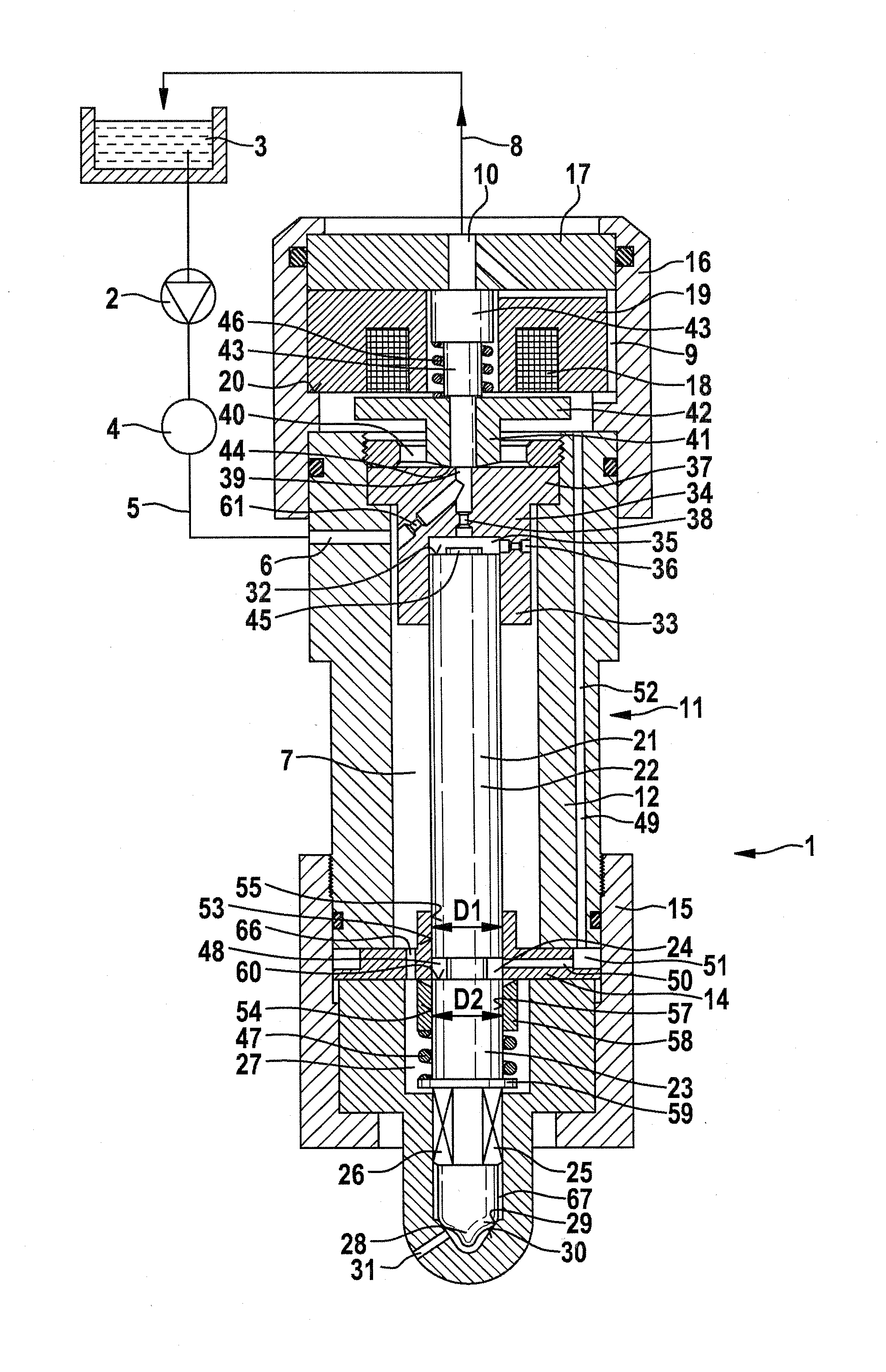
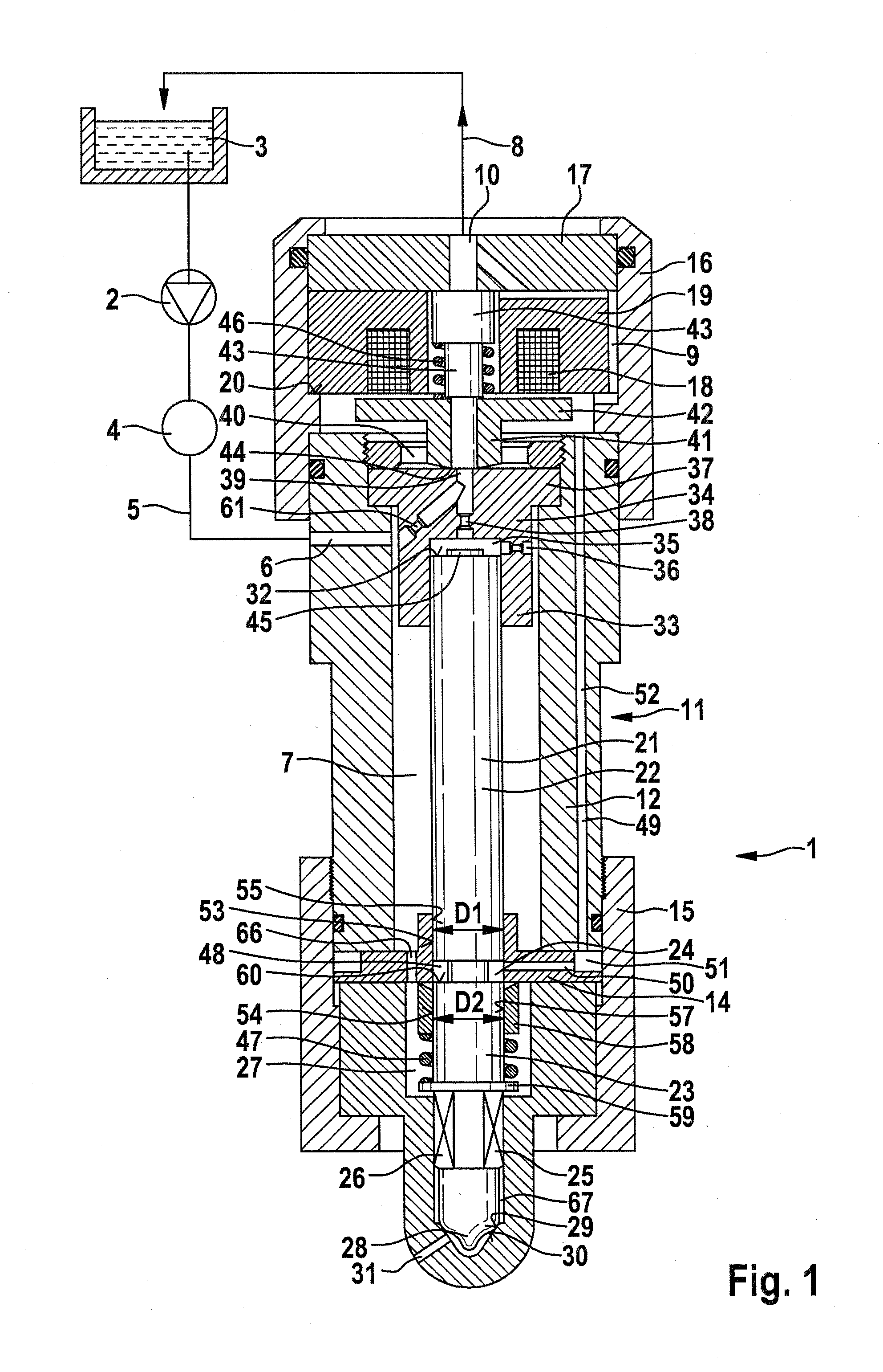
[0019]In FIG. 1, a fuel injector 1 embodied as a common rail injector is shown, for injecting fuel into a combustion chamber, not shown, of an internal combustion engine of a motor vehicle. A high-pressure pump 2 delivers fuel from a supply container 3 into a high-pressure fuel reservoir 4 (rail). In the rail, fuel, especially diesel fuel or gasoline, is stored at high pressure, which in this exemplary embodiment is above 2000 bar.

[0020]The fuel injector 1, along with other fuel injectors, not shown, is connected to the high-pressure fuel reservoir 4 via a supply line 5. The supply line 5 discharges into a supply conduit 6 of the fuel injector 1 which discharges into a high-pressure chamber 7 of the fuel injector 1. The high-pressure chamber 7 forms a mini-rail, because of which pressure fluctuations are minimized. By means of a return line 8, a low-press...


PUM


Abstract

The invention relates to a fuel injector and, in particular, to a common-rail injector for injecting fuel into a combustion chamber of an internal combustion engine with a multi-part injection valve element, which can be adjusted between an open position and a closed position. A first part and a second part of the injection valve element are coupled to one another via a hydraulic coupler, which is bounded radially by a first guide for the first part and by a second guide for the second part. According to the invention, at least some sections of the first and the second guide are surrounded at their outer radii by fuel under high pressure, and the pressure realized in the hydraulic coupler is lower than the pressure radially outside the guides.

Description

PRIOR ART[0001]The invention relates to a fuel injector for injecting fuel into a combustion chamber of an internal combustion engine, as generically defined by the preamble to claim 1.[0002]From German Patent Disclosure DE 10 2006 008 648 A1, a fuel injector embodied as a common rail injector is known that has a two-part injection valve element, which is triggerable via a control valve (servo valve). The two parts of the injection valve element are coupled to one another via a hydraulic coupler. In the state of repose of the fuel injector, rail pressure prevails in the hydraulic coupler. The known fuel injector has little leakage; that is, it is embodied with a low-pressure stage. To attain an adequate hydraulic needle closing force, a closing throttle restriction is placed in a connecting conduit that supplies a lower nozzle chamber with fuel. One disadvantage of the known fuel injector is that upon triggering of the injection valve element, the two parts of the injection valve el...

Claims


Application Information

Patent Timeline
IPC IPC(8): F02M61/04
CPCF02M47/027F02M61/12F02M63/0005F02M63/0015F02M63/008F02M2200/704F02M2200/705F02M2547/003F02M57/025F02M2200/703F02M2200/304
Inventor BURGER, MATTHIASMAGEL, HANS-CHRISTOPH
Owner ROBERT BOSCH GMBH
Why Eureka
Try Eureka