Molten metal containment structure having flow through ventilation

a technology of containment structure and metal, which is applied in the direction of manufacturing converters, charge manipulation, furnaces, etc., can solve the problems of unsafe equipment operators' operating temperature, cracks in the vessel, and the refractory vessel may become extremely hot during use, so as to reduce the temperature of the casing, lower the melting point, and the effect of increasing the melting poin

Active Publication Date: 2011-06-16
NOVELIS INC
View PDF10 Cites 48 Cited by
  • Summary
  • Abstract
  • Description
  • Claims
  • Application Information

AI Technical Summary

Benefits of technology

[0014]A preferred embodiment provides a molten metal distribution structure having a ceramic trough having sides and a bottom, and an external surface, and a metal casing for the ceramic trough having an internal surface at least partially surrounding the external surface of the ceramic trough at a distance therefrom forming a spacing between the trough and the casing. A layer of thermal insulation material is positioned in the spacing between the ceramic trough and the casing. The layer of insulation material adjacent to the sides of the ceramic trough is made narrower than the spacing at these points to form an upwardly-extending continuous unfilled gap within the structure at the sides thereof. The gap communicates with lower and upper openings in the casing positioned to permit external air to enter and flow upwardly through the gap. The gap creates and air flow through the casing that reduces the tempera...

Problems solved by technology

Metal containment structures of this kind suffer from the disadvantage that the refractory vessel may become extremely hot during use due to contact with the molten metal (e.g. 680° C. to 750° C. when conveying molten aluminum or aluminum alloys).
If this heat is transferred to the outer metal casing of the structure, the metal casing may be subjected to expansion, warping or distortion which, in turn, may cause cracks to form in the vessel or, if the refractory vessel is made in sections, may cause gaps to form between the sections, thereby allowing molten metal to leak from the vessel into the casing.
Additionally, the outer surfaces of the casin...

Method used


Image

  • Molten metal containment structure having flow through ventilation
  • Molten metal containment structure having flow through ventilation
  • Molten metal containment structure having flow through ventilation

Examples


Embodiment Construction

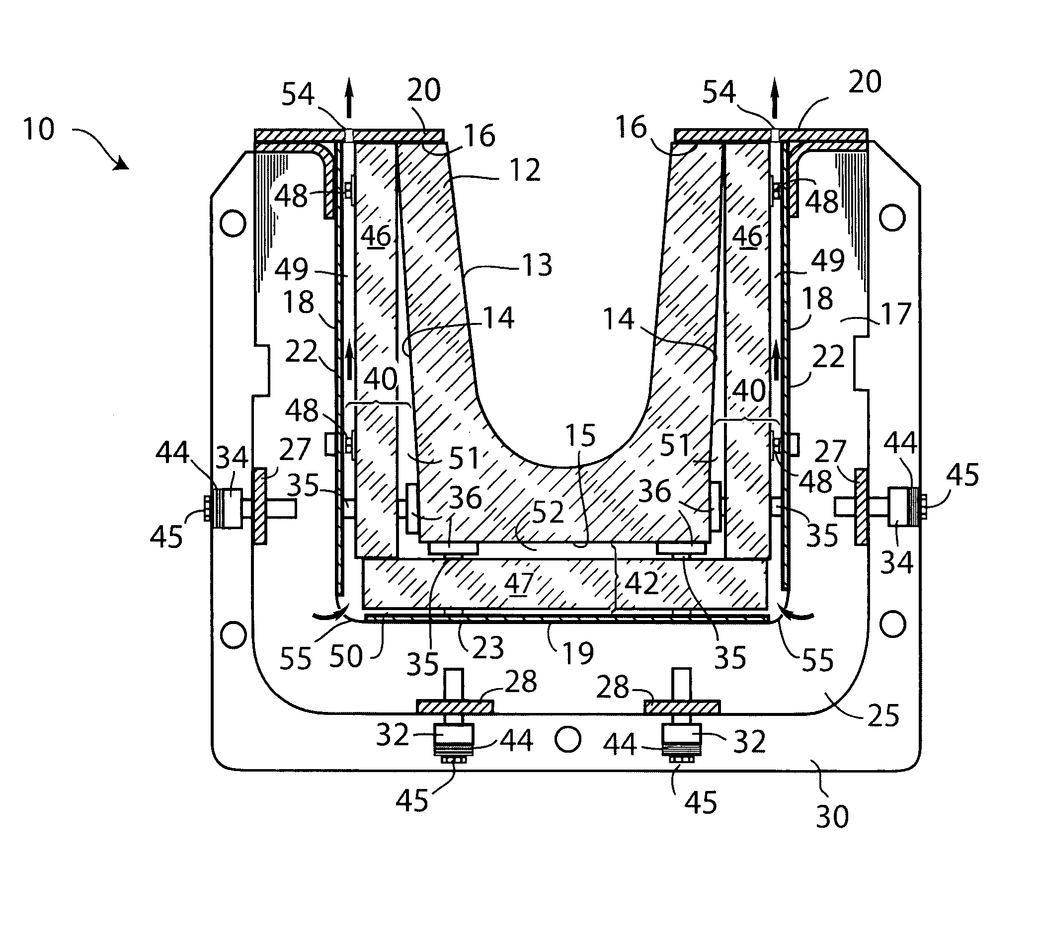
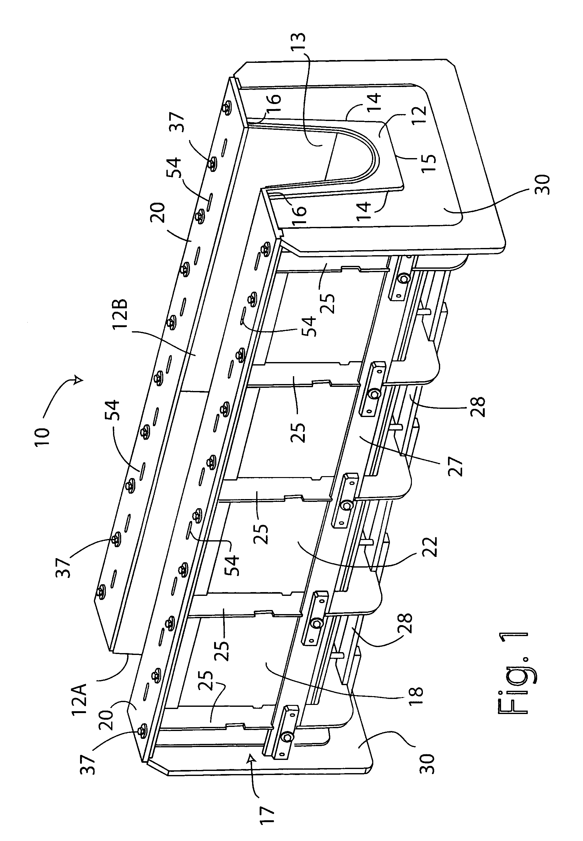
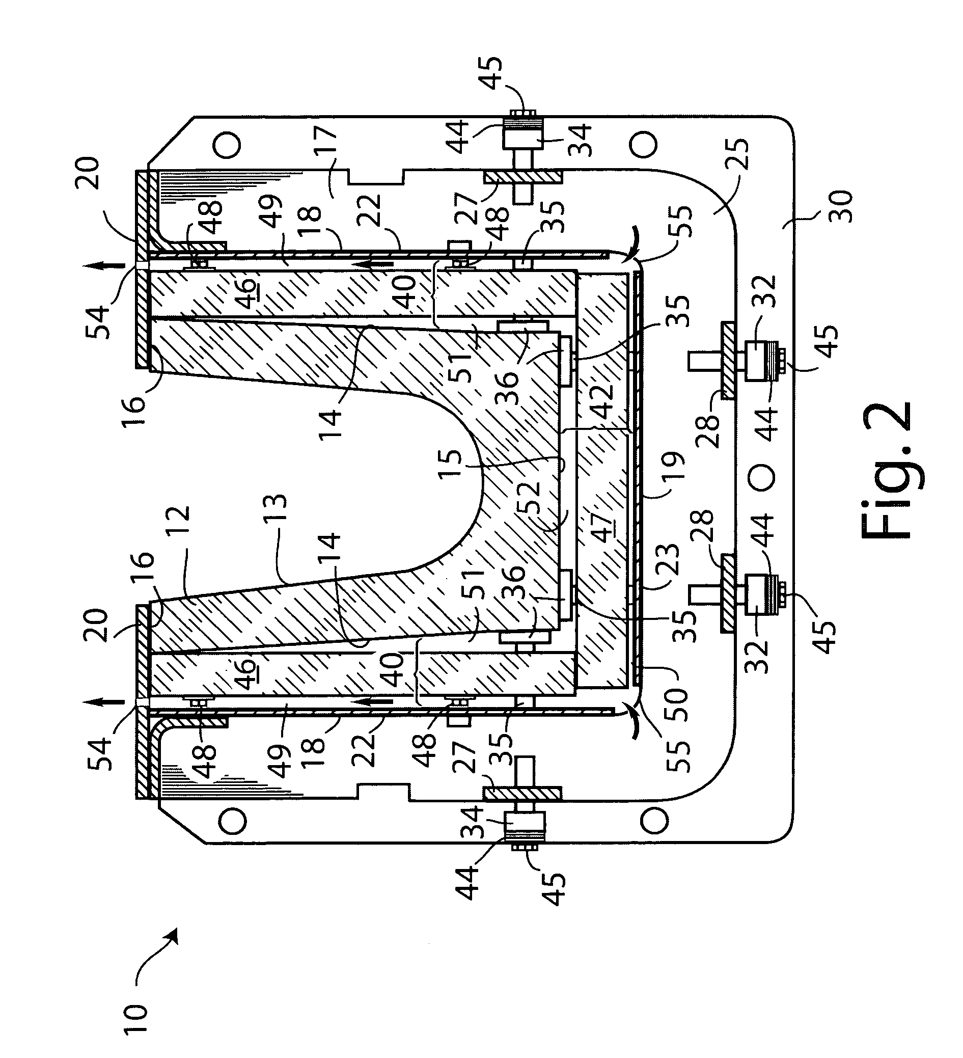
[0008]An exemplary embodiment of the invention provides a molten metal containment (e.g. holding or distribution) structure including a refractory molten metal containment vessel having an external surface, and a metal casing for the vessel having an internal surface at least partially surrounding the external surface of the vessel at a distance therefrom forming a spacing between the vessel and the casing. The spacing includes an unobstructed upwardly extending gap that is vented to the exterior of the structure by upper and lower openings in the casing. Preferably, a layer of insulating material is positioned in the spacing between the internal surface of the casing and the external surface of the vessel, the layer of insulating material being narrower than the spacing at least at upwardly extending sides of the casing, thereby forming the unobstructed gap.

[0009]The unobstructed gap is preferably formed between the layer of insulating material and the internal surface of the metal...


PUM

PropertyMeasurementUnit
Flow rateaaaaaaaaaa
Structureaaaaaaaaaa
Volumeaaaaaaaaaa

Abstract

Exemplary embodiments of the invention provide a molten metal containment structure including a refractory molten metal containment vessel having an external surface, and a metal casing for the vessel having an internal surface at least partially surrounding the external surface of the vessel at a distance therefrom forming a spacing between the vessel and the casing. The spacing includes an unobstructed upwardly extending gap that is vented to the exterior of the structure by upper and lower openings in the casing. A layer of insulating material is preferably positioned in the spacing between the internal surface of the casing and the external surface of the vessel, with the layer of insulating material being narrower than the spacing at least at upwardly extending sides of the casing, thereby forming the unobstructed gap. The vessel may be a metal conveying trough, a housing for a metal filter, a container for a metal degasser unit, a crucible, or the like.

Description

CROSS-REFERENCE TO RELATED APPLICATION[0001]This application claims the priority right of provisional U.S. patent application Ser. No. 61 / 283,887 filed on Dec. 10, 2009 by applicants herein. The entire contents of application Ser. No. 61 / 283,887 are specifically incorporated herein for all purposes by this reference.BACKGROUND OF THE INVENTION[0002](1) Field of the Invention[0003]The present invention relates to molten metal containment systems and structures used, for example, for conveying molten metal from one location to is another, e.g. from a metal melting furnace to a metal casting mold or casting table. More particularly, the invention relates to such structures containing a refractory (usually ceramic) vessel, e.g. a metal distribution trough, crucible, or the like, contained within an outer metal casing used to support, protect and locate the refractory vessel.[0004](2) Description of the Related Art[0005]Metal containment structures of this kind suffer from the disadvanta...

Claims


Application Information

Patent Timeline
IPC IPC(8): C21B7/04C21B7/16
CPCB22D11/103B22D35/04F27D3/14C21C5/5294C21B7/14Y02P10/20F27D1/12F27D1/14
Inventor REEVES, ERIC W.HYMAS, JASON D.TINGEY, JOHN STEVEN
Owner NOVELIS INC
Why Eureka
Try Eureka