Displacement measurement device, exposure apparatus, and working device

a displacement measurement and interferometer technology, applied in the direction of interferometers, instruments, printing, etc., can solve the problems of manufacturing errors, and difficult to create a grating pattern with even line widths and thicknesses

Active Publication Date: 2011-06-16
CANON KK
View PDF13 Cites 34 Cited by
  • Summary
  • Abstract
  • Description
  • Claims
  • Application Information

AI Technical Summary

Problems solved by technology

However, in manufacturing a scale with a laser drawing method, beam diameters can change on the process face, resulting from output changes of a semiconductor laser or optical systems of a drawing device, so creating a grating pattern having even line widths and thicknesses can be difficult.
Also, with an etching method, creating a grating pattern having even line widths and thicknesses can be difficult, due to the influence from etching scattering on the wall portion of the grating pattern side or the unevenness of the thickness of a metallic layer or the like.
Accordingly, manufacturing error such as irregularities in the line width of the grating pattern, varying thicknesses, and so forth, occur.
Therefore, measurement error of varying magnitudes can occur depending on the measurement position on the scale, and accurately performing displacement measurement of an object becomes difficult.
Also, measurement error can occur of changes according to measurement position on the scale, not only from changes to the alternating-current components and changes to the direct-current components of the reference signal waveforms, but also from changes to phase difference of superpositioned diffracted light.
Also, with a method in which obtained interference signals are corrected as with Japanese Patent Laid-Open No. 2008-185474, measurement error due to manufacturing error in the scale cannot be sufficiently corrected, so highly precise measurement is difficult.

Method used


Image

  • Displacement measurement device, exposure apparatus, and working device
  • Displacement measurement device, exposure apparatus, and working device
  • Displacement measurement device, exposure apparatus, and working device

Examples


first embodiment

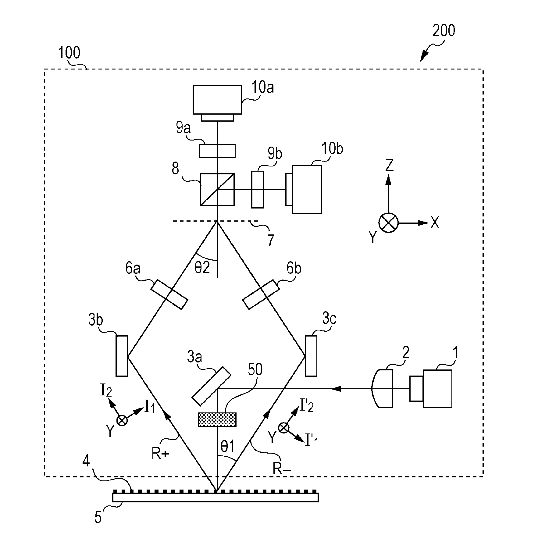
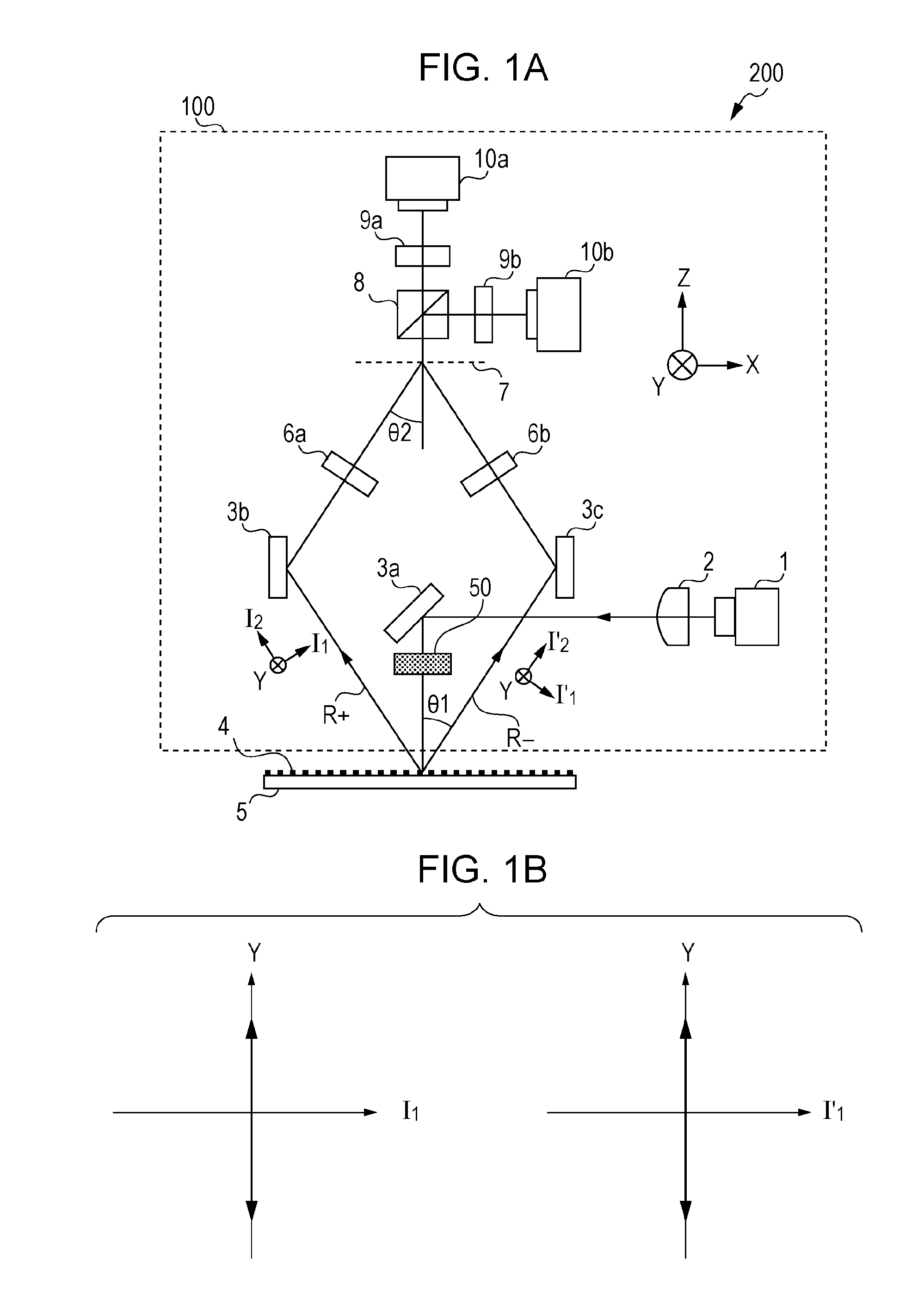
[0019]FIG. 1A is a schematic diagram showing a configuration of a displacement measurement device 200 serving as one aspect of the present invention. In FIG. 1A, the direction that is orthogonal as to the paper face will be the Y-direction, the direction that is orthogonal to the Y-direction and that is in a horizontal direction to the paper face will be the X-direction, and the direction that is orthogonal to the X-direction and Y-direction and that is vertical on the paper face will be the Z-direction. The displacement measurement device 200 is a device made up of a detecting head 100 and scale 5, and measures relative displacement amount in the X-direction of the detecting head 100 and scale 5. The detecting head 100 is made up of a laser light source 1, collimator lens 2, mirror 3, polarizer 50, λ / 4 plate 6, reference diffraction grating 7 (optical element), beam splitter (BS) 8, polarizer 9, and photodetector 10. Note that the mirror 3, λ / 4 plate 6, polarizer 9, and photodetect...

second embodiment

[0045]Next, a displacement measurement device having a configuration different from the first embodiment will be described as a second embodiment of the present invention.

[0046]FIG. 5A is a schematic diagram of a displacement measurement device 201 showing a configuration of the second embodiment according to the present invention. The displacement measurement device 201 is made up of a detecting head 101 and scale 5. The point differing from the first embodiment is the placement of the polarizer 50. The displacement measurement device according to the present invention has polarizers 50a and 50b instead of the polarizer 50 in FIGS. 1A and 1B.

[0047]According to the present embodiment, two polarizers 50a and 50b are used to transform positive / negative 1st-order diffracted light R+, R− into linearly polarized light in the same polarization direction. At this time, the polarization direction of the linear polarization differs from the first embodiment, and does not need to match the gr...

third embodiment

[0056]Next, a case of applying the displacement measurement device of the present invention to a stage position measurement device of an exposure apparatus will be described as a third embodiment of the present invention.

[0057]FIGS. 6A and 6B are diagrams showing a configuration of the displacement measurement device of the present invention which has an exposure apparatus. As shown in FIG. 6A, the exposure apparatus has a light source unit 800, reticle stage RS holding a reticle 14, projection optical system 15, scale 5, wafer stage WS holding a wafer 36, and detecting head 102 mounted on the wafer stage WS. The displacement measurement device can apply the displacement measurement device described in the first or second embodiment. Note that the wafer stage WG is made up of a fine-motion stage and a coarse-motion stage, and the detecting head 102 is mounted on the fine-motion stage. The wafer 36 is coated with photoresist.

[0058]A stage control unit 1000 is electrically connected t...


PUM


Abstract

A device has a scale on which a grating pattern is formed, a light source to irradiate light on the scale, a wavelength plate to transform multiple diffracted lights from the light source into circular polarized light, respectively, an optical element to superposition and cause interference of the multiple diffracted lights, and a photodetector to receive the interfered light. Also, a generating unit to generate linearly polarized light by the light from the light source, so that the multiple diffracted lights input to the wavelength plate become linearly polarized light with a same mutual polarization direction.

Description

BACKGROUND OF THE INVENTION[0001]1. Field of the Invention[0002]The present invention relates to a grating interferometry-type displacement measurement device.[0003]2. Description of the Related Art[0004]Heretofore, a displacement measurement device (encoder) such as a rotary encoder or linear encoder has been widely used to measure displacement amounts such as the position information, movement amount, rotation amount, and so forth of a physical object. A grating interferometry-type encoder is one of these serving as an encoder to measure displacement amount with a high degree of precision. A grating interferometry-type encoder is a device that inputs coherent light to a scale where is formed a grating pattern (i.e. diffraction grating), interference is caused with diffracted light which has been diffracted by a grating pattern, and displacement amount of the scale is obtained based on the phase changes of the obtained interfered light.[0005]Japanese Patent Laid-Open No. 2007-29273...

Claims


Application Information

Patent Timeline
Patent Type & Authority Applications(United States)
IPC IPC(8): G03B27/32G01B9/02
CPCG01D5/38G03F7/70775G01B2290/70G01B9/02097
Inventor YAMAGUCHI, WATARUMATSUMOTO, TAKAHIRO
Owner CANON KK
Why Eureka
Try Eureka