Splash guard for a floor cleaning machine

Inactive Publication Date: 2011-06-23
ALLARD MICHAEL
View PDF13 Cites 0 Cited by
  • Summary
  • Abstract
  • Description
  • Claims
  • Application Information

AI Technical Summary

Benefits of technology

[0006]The object of the present invention is to provide an improved splash guard designed to prevent cleaning substances such as wax, liquid cleanser, debris and the like from being spattered and sprayed fo

Problems solved by technology

This is particularly undesirable as the splattered area or objects then need to be re-cleaned, resulting in time consuming additional work for the cleaning personnel.
In addition, the splattered material can stain or otherwise permanently damage baseboards, furniture and the like.
Floor cleaning machines may also be hazardous to the operator because t

Method used


Image

  • Splash guard for a floor cleaning machine
  • Splash guard for a floor cleaning machine
  • Splash guard for a floor cleaning machine

Examples


Embodiment Construction

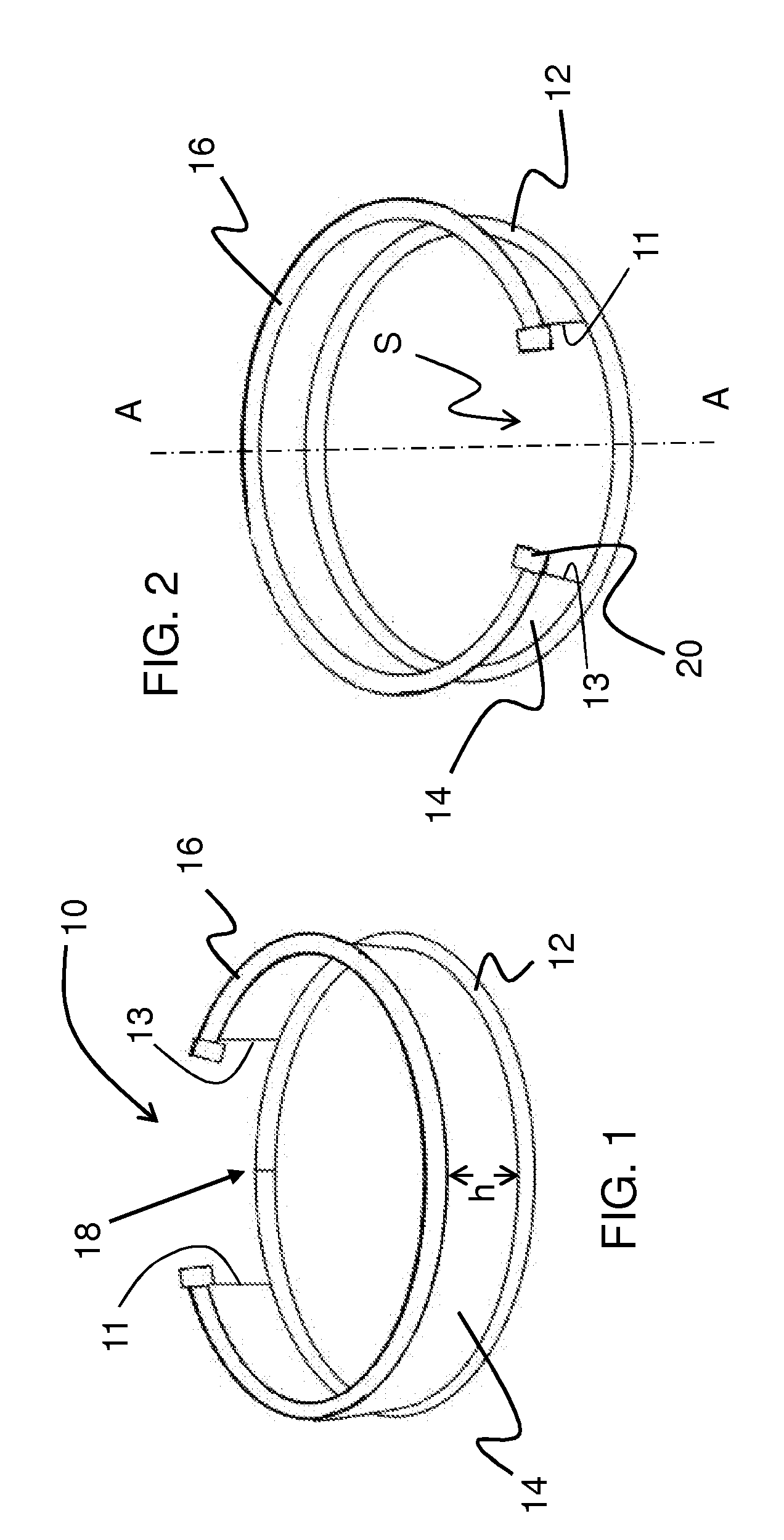
[0025]A front view of the splash guard apparatus 10 is shown in FIG. 1 and consists of a circumferential lower bumper 12, a pliable housing 14, and a partially circumferentially encompassing upper tubular bumper 16. The pliable housing 14 is attached to and substantially around a portion of the ring that is formed when the lower bumper 12 is connected at the quick connection point 18. The pliable housing 14 is made from a material flexible enough to bend in a radial manner around a central axis A, but rigid enough so that the housing 14 does not bend or collapse in an axial manner relative to axis A. The axial height h of the housing may be from 1-10 inches but is preferably about 3-6. The upper tubular bumper 16 may attach to the full length of the pliable housing 14 or may extend ½″ to 1½″ past the ends of the housing 14 in order to attach bumper caps 20 that enclose the tubular bumper ends for protection from scraping or gouging by the tubular ends.

[0026]The rear view of the spla...


PUM

PropertyMeasurementUnit
Thicknessaaaaaaaaaa
Diameteraaaaaaaaaa
Shapeaaaaaaaaaa

Abstract

The present invention relates to a splash guard that partially encircles a rotary floor cleaning apparatus allowing for support wheels to maneuver the apparatus when the rotary brushes are not in operation. The splash guard prevents cleansing material or debris from being splattered onto walls and other surfaces adjacent to the surface being cleaned.

Description

FIELD OF THE INVENTION[0001]The present invention relates to a guard for a floor cleaning or buffing machine and more particularly to a splash guard that at least partially encompasses a the scrubber pad of a rotary floor cleaning apparatus so as to prevent cleansing material or debris from being splattered onto walls and other surfaces adjacent to the surface being cleaned.BACKGROUND OF THE INVENTION[0002]Floor cleaning machines typically comprise a frame supporting a single or a number of motor-driven rotary pads or brushes, a motor, and a handle pivotally mounted to the frame. Because floor cleaning machines are quite heavy there are generally two support wheels attached to the back of machine that allow the machine to be tilted back onto the wheels and then more efficiently and easily moved when the machine is not undertaking a floor cleaning operation. When the device is in operation, it is set in an upright position and supported on the floor by the rotary pad or brush(es).[00...

Claims


Application Information

Patent Timeline
IPC IPC(8): A47L25/00B23P17/04
CPCA47L11/283Y10T29/49826A47L11/4077
Inventor ALLARD, MICHAEL
Owner ALLARD MICHAEL
Why Eureka
Try Eureka