
Electromagnetic radiation absorber and method for absorbing electromagnetic radiation

a technology of electromagnetic radiation absorber and electromagnetic radiation absorber, which is applied in the direction of antennas, magnetic bodies, and non-polar magnetic fields, can solve the problems of unsatisfactory achieve high magnetic permeability materials, and high electromagnetic radiation absorbing properties.

Inactive Publication Date: 2011-06-23
NITTO DENKO CORP
View PDF17 Cites 8 Cited by
  • Summary
  • Abstract
  • Description
  • Claims
  • Application Information

AI Technical Summary

Benefits of technology

The present invention provides an electromagnetic radiation absorber and a method for absorbing electromagnetic radiation that can absorb wideband electromagnetic radiation, including low-frequency electromagnetic radiation. The absorber is made of a composite of high permittivity dielectric material and high magnetic permeability material arranged in a three-dimensional manner. The absorber can be made into a thin film and can reduce weight. The technical effect of the invention is to improve the electromagnetic radiation absorbing property of the absorber with respect to a wideband of frequency, including low-frequency electromagnetic radiation.

Problems solved by technology

However, the electromagnetic radiation absorber that utilizes the above conditional expression for no-reflection has an excellent electromagnetic radiation absorbing property with respect to electromagnetic radiation of specific narrow-band frequency, but with respect to electromagnetic radiation of other band of frequency, the electromagnetic radiation absorbing property thereof is unsatisfactory.

Method used


Image

  • Electromagnetic radiation absorber and method for absorbing electromagnetic radiation
  • Electromagnetic radiation absorber and method for absorbing electromagnetic radiation
  • Electromagnetic radiation absorber and method for absorbing electromagnetic radiation

Examples


first embodiment

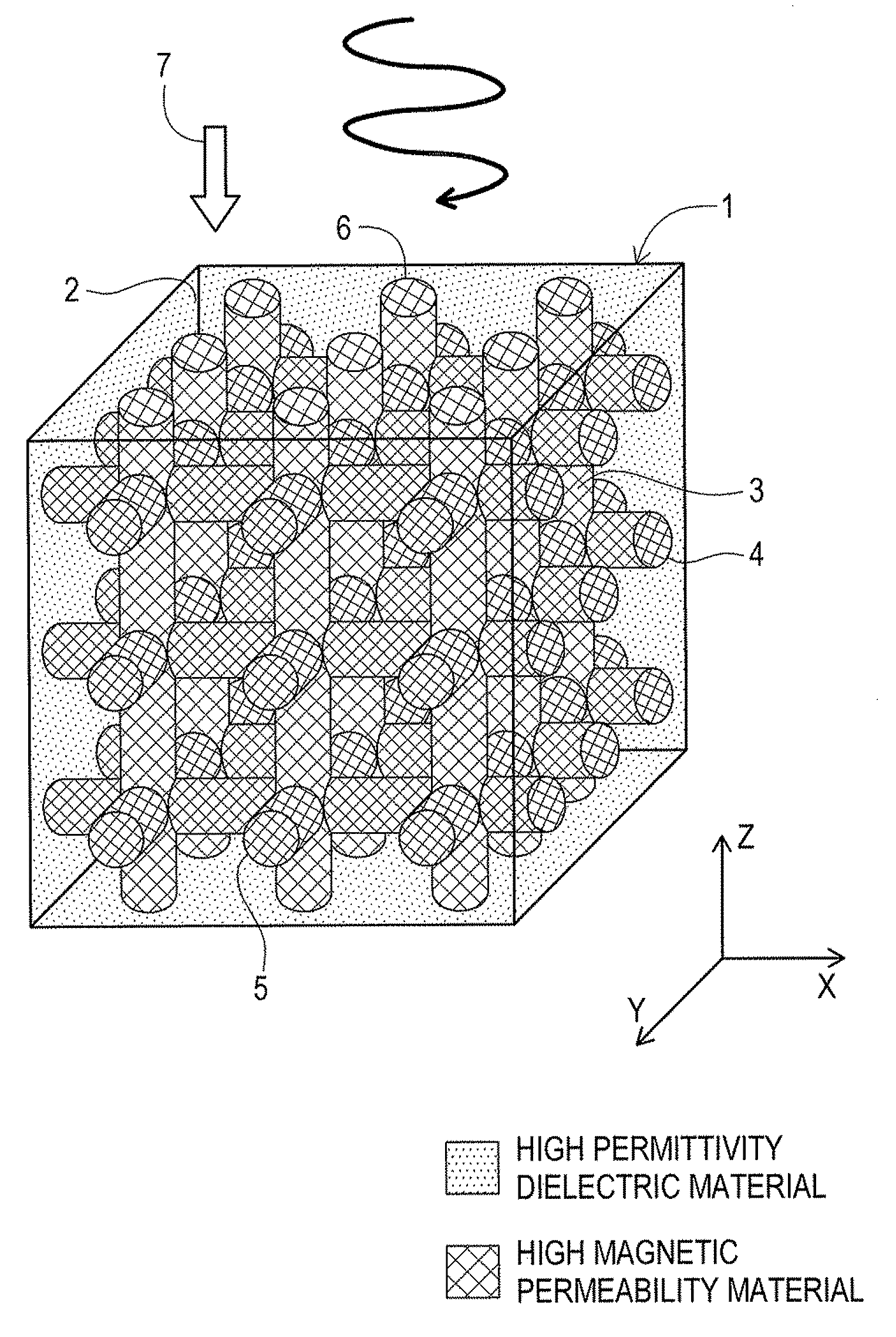
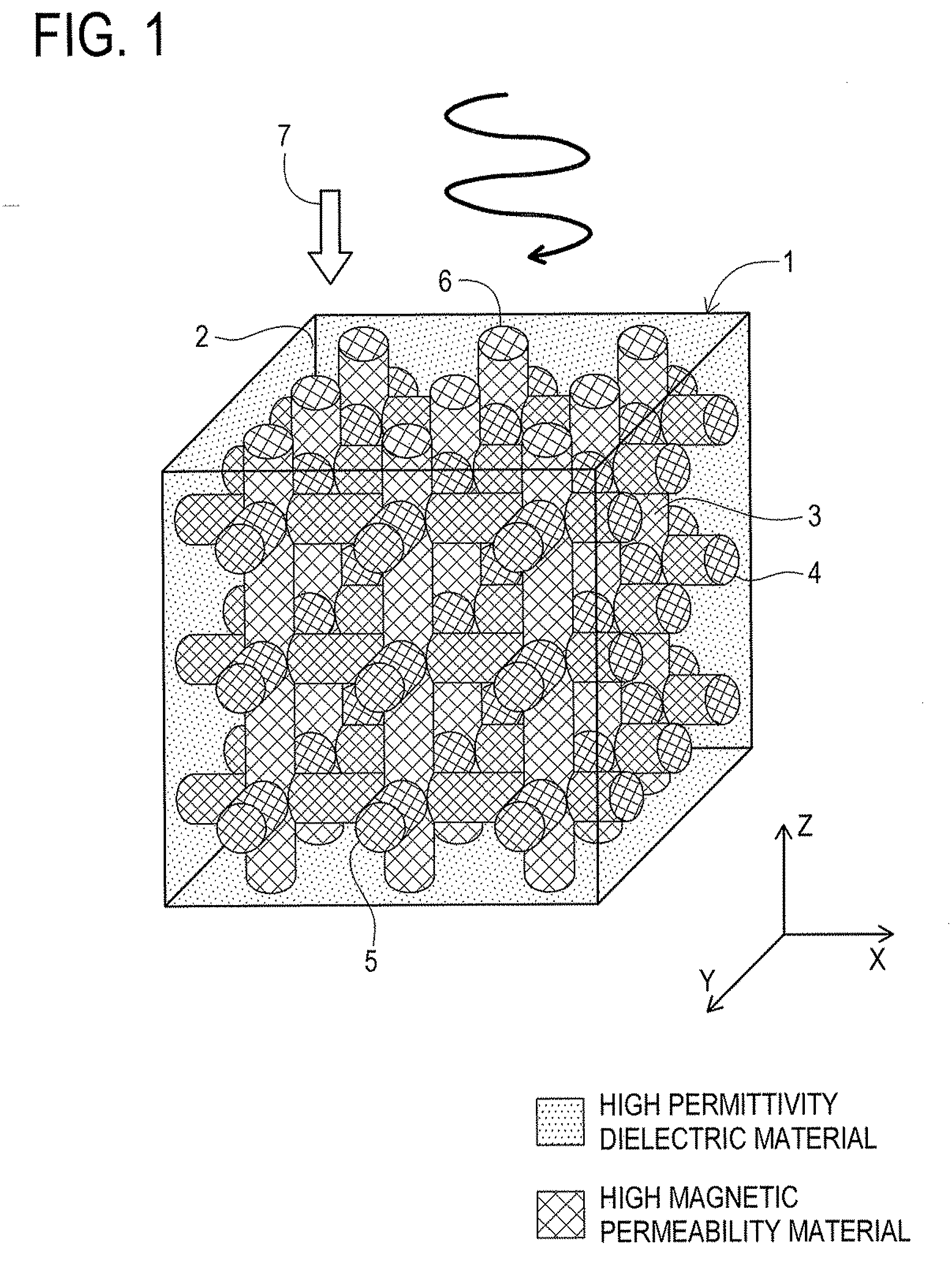
[0042]First, details of an electromagnetic radiation absorber 1 according to the first embodiment will be given while referring to FIG. 1. FIG. 1 is an explanatory view depicting the electromagnetic radiation absorber 1 according to the first embodiment.

[0043]As illustrated in FIG. 1, the electromagnetic radiation absorber 1 according to the first embodiment is configured with a composite where base material 2 formed of high permittivity dielectric material and having a cubical shape and filler 3 formed of high magnetic permeability material and having a cylindrical shape are combined. In the first embodiment, for instance, barium titanate (at measurement frequency 45 MHz, value of real part of complex relative permittivity ∈r: “90”, value of real part of complex relative permeability μr: “1”) may be used as the high permittivity dielectric material. Also, as the high magnetic permeability material, for instance, ferrite (at measurement frequency 45 MHz, value of real part of comple...

second embodiment

[0069]Next, details of an electromagnetic radiation absorber 41 according to the second embodiment will be given while referring to FIG. 7. FIG. 7 is an explanatory view depicting the electromagnetic radiation absorber 41 according to the second embodiment.

[0070]As illustrated in FIG. 7, the electromagnetic radiation absorber 41 according to the second embodiment is configured with a composite where base material 42 formed of high magnetic permeability material and having a cubical shape and filler 43 formed of high permittivity dielectric material and having a cylindrical shape are combined. In the second embodiment, for instance, ferrite (at measurement frequency 45 MHz, value of real part of complex relative permittivity ∈r: “2”, value of real part of complex relative permeability μr: “90”) may be used as the high magnetic permeability material. Also, as the high permittivity dielectric material, for instance, water (at measurement frequency 45 MHz, value of real part of complex ...

third embodiment

[0077]Next, details of an electromagnetic radiation absorber 51 according to the third embodiment will be given while referring to FIG. 8. FIG. 8 is an explanatory view depicting an electromagnetic radiation absorber 51 according to the third embodiment with a partial enlargement.

[0078]As illustrated in FIG. 8, the electromagnetic radiation absorber 51 according to the third embodiment is configured with a composite where first cord-shaped members 52 formed of high permittivity dielectric material and second cord-shaped members 53 formed of high magnetic permeability material are combined. In the third embodiment, for instance, barium titanate (at measurement frequency 45 MHz, value of real part of complex relative permittivity ∈r: “90”, value of real part of complex relative permeability μr: “1”) or water (at measurement frequency 45 MHz, value of real part of complex relative permittivity ∈r: “80.4”, value of real part of complex relative permeability μr: “1”) may be used as high ...


PUM


Abstract

An electromagnetic radiation absorber is made up of a composite of base material and filler. The base material is formed of high permittivity dielectric material and formed in a cubic shape. The filler is formed of high magnetic permeability material and fills in long holes formed inside the base material in three directions. In the composite, the high permittivity dielectric material and the high magnetic permeability material are arranged in a three-dimensionally continuous manner. Accordingly, a thinned and light-weighted electromagnetic radiation absorber and a method for absorbing electromagnetic radiation are provided which have a high electromagnetic radiation absorbing property with respect to electromagnetic radiation of wide band including electromagnetic radiation of low frequency.

Description

TECHNICAL FIELD[0001]The present invention relates to an electromagnetic radiation absorber and a method for absorbing electromagnetic radiation which make it possible to absorb wideband electromagnetic radiation emitted from electronic components such as motors.BACKGROUND ART[0002]Recently there have been not a few cases where electromagnetic radiation emitted from electronic devices such as driving motors and computers disturbs normal operation of other electronic devices. Accordingly, countermeasures are conventionally taken to prevent ill effects from the electromagnetic radiation, through surrounding such an electronic device or forming a dividing wall with an absorber that absorbs electromagnetic radiation (refer to Japanese Laid-Open Patent Application 2004-207328, for instance). In such an electromagnetic radiation absorber, it is important to take in incident electromagnetic radiation to the inside of the absorber without reflection as well as to attenuate the incident elec...

Claims


Application Information

Patent Timeline
Patent Type & Authority Applications(United States)
IPC IPC(8): H05K9/00B32B1/00
CPCB82Y25/00H01Q17/004H01F1/0081
Inventor KUME, KATSUYATADA, MASATAKAERIGUCHI, FUYUKIHATANAKA, TAKEZOFUKUDA, YUUKIHOSHINO, TOSHINOBUHASHIMOTO, OSAMUSAKUMO, YUICHI
Owner NITTO DENKO CORP
Learn More