Exhaust gas denitrizer

a technology of exhaust gas and denitrizer, which is applied in the direction of emission prevention, separation process, lighting and heating apparatus, etc., can solve the problems of catalyst performance degradation, and achieve the effect of reducing duct pressure loss and reducing the temperature of rejoined exhaust gas

Active Publication Date: 2011-06-23
BABCOCK HITACHI KK
View PDF3 Cites 4 Cited by
  • Summary
  • Abstract
  • Description
  • Claims
  • Application Information

AI Technical Summary

Benefits of technology

[0019]The present invention can even out the temperature of the rejoined exhaust gas quickly while curbing increases in duct pressure losses.

Problems solved by technology

The acidic ammonium sulfate, which is in a liquid state, adheres to surfaces of the catalyst and thereby covers active catalyst sites, resulting in performance degradation of the catalyst.

Method used


Image

  • Exhaust gas denitrizer
  • Exhaust gas denitrizer
  • Exhaust gas denitrizer

Examples


first example

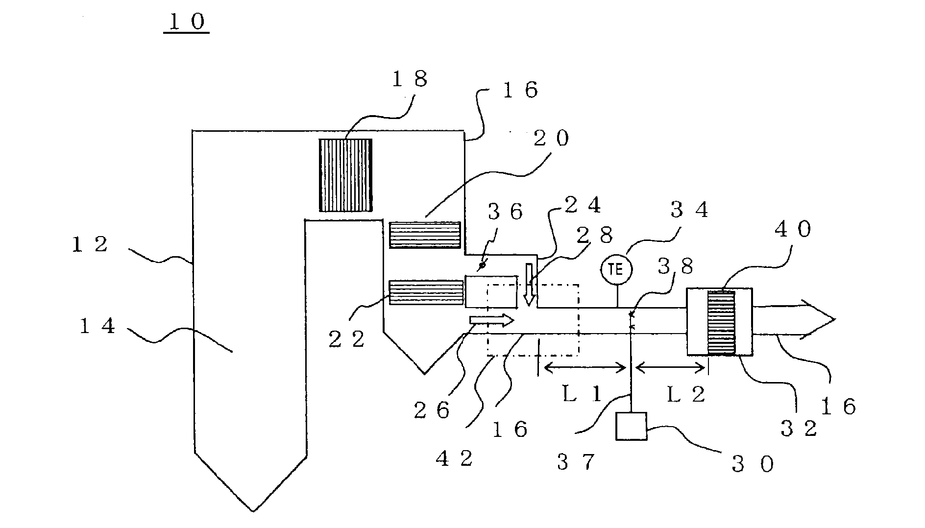
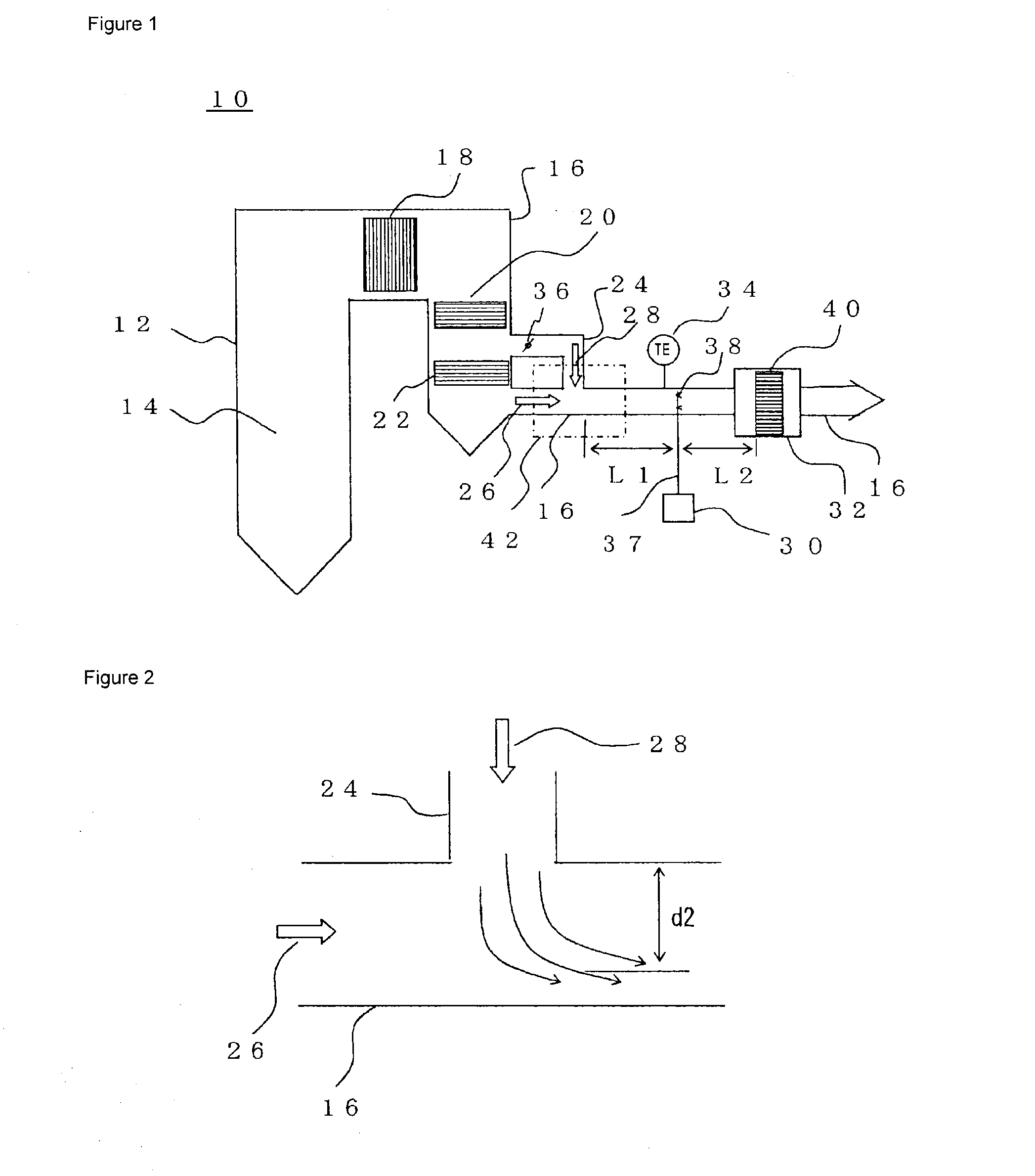
[0049]FIG. 3 is an enlarged view of the meeting place 42 between the main duct 16 and bypass duct 24 shown in FIG. 1 and is a diagram showing a first example of the characteristic portion of the exhaust gas denitrizer. As shown in FIG. 3, at the meeting place between the main exhaust gas 26 and bypass exhaust gas 28 in the main duct 16, three partition plates 44 are installed with plate surfaces turned to the inflow direction of the bypass exhaust gas 28, partitioning a main exhaust gas channel into a plurality of sub-channels along the flowing direction of the main exhaust gas 26. Also, upstream-side ends of the partition plates 44 along the inflow direction of the main exhaust gas face the incoming bypass exhaust gas by being shifted from one another toward the upstream side of the main exhaust gas starting from the inflow side of the bypass exhaust gas.

[0050]The partition plates 44 installed in this way cause the bypass exhaust gas 28 flowing into the main duct 16 to come into co...

second example

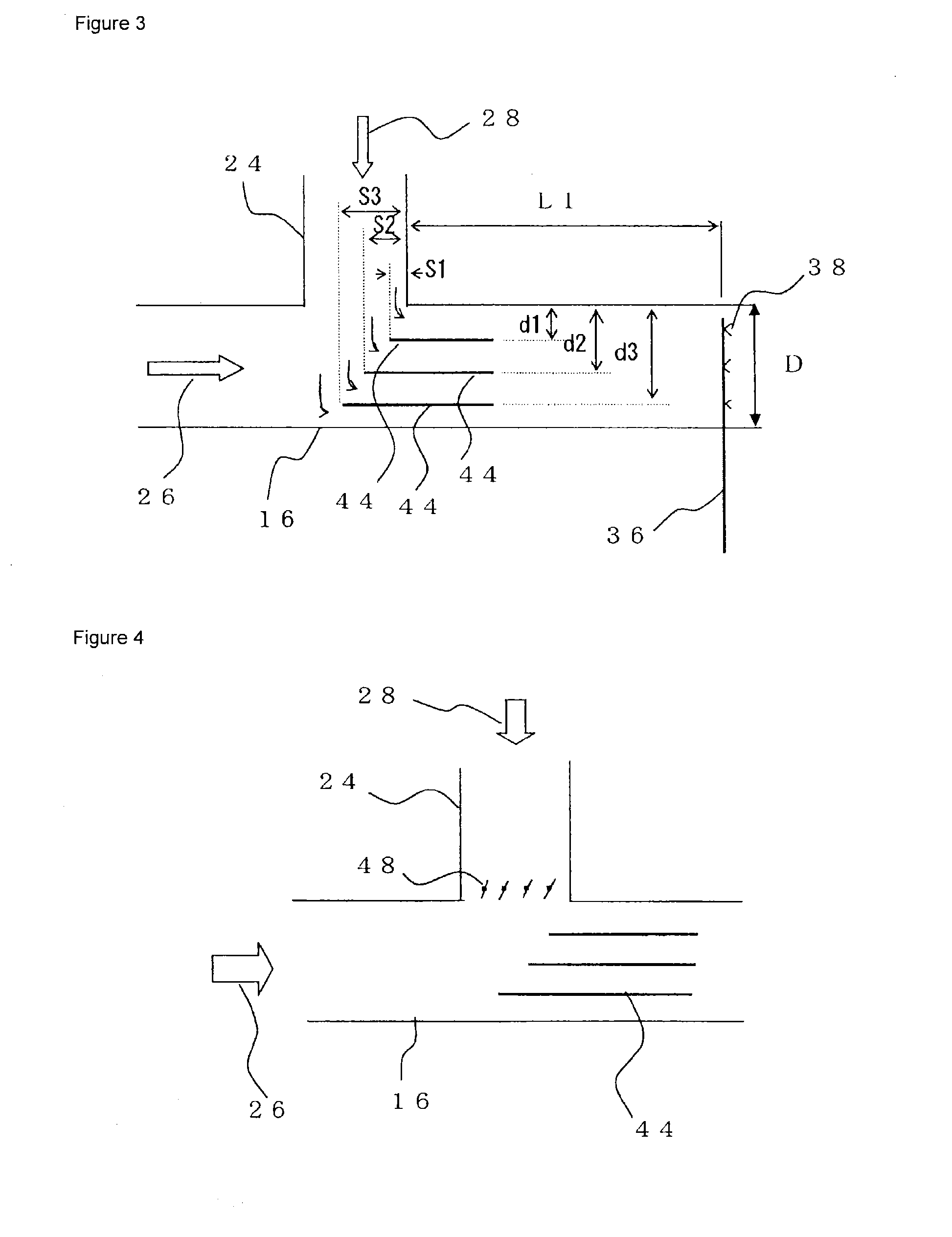
[0057]FIG. 4 is an enlarged view of the meeting place 42 between the main duct 16 and bypass duct 24 shown in FIG. 1 and is a diagram showing a second example of the characteristic portion of the exhaust gas denitrizer. In the present example, in addition to installing the partition plates 44 as in the case of the first example, adjustment vanes are installed in the bypass duct 24. Only differences from the first example will be described, and description of the other parts will be omitted.

[0058]As shown in FIG. 4, turnable adjustment vanes 48 are installed at the meeting place 42 of the bypass duct 24 with the main duct 16 to adjust flow direction of the bypass exhaust gas 28 flowing into the main duct 16.

[0059]When the bypass damper 36 is installed in the bypass duct 24 as described above and the flow rate of the bypass exhaust gas 28 is adjusted by changing a tilt angle based on detected values of the temperature sensor 34, the flow ratio between the main exhaust gas 26 and bypas...

third example

[0065]FIG. 5 is an enlarged view of the meeting place 42 between the main duct 16 and bypass duct 24 shown in FIG. 1 and is a diagram showing a third example of the characteristic portion of the exhaust gas denitrizer. The present example is a variation of the first example and uses different forms of the main duct 16 and partition plates 44. Therefore, only differences from the first example will be described, and description of the other parts will be omitted.

[0066]As shown in FIG. 5, according to the present example, the main duct 16 is shaped to gradually increase in diameter as it goes downstream from near the meeting place of the two types of exhaust gas. In this case, being installed with the plate surfaces turned to the inflow direction of the bypass exhaust gas 28, the partition plates 44 extend straight along the flowing direction of the main exhaust gas 26 near the meeting place, then extend along the flowing direction by spreading with increases in the diameter of the ma...


PUM

PropertyMeasurementUnit
exhaust gas temperatureaaaaaaaaaa
concentrationsaaaaaaaaaa

Abstract

An exhaust gas denitrizer removes nitrogen oxides from rejoined exhaust gas using a denitrification reactor after supplying ammonia gas to the rejoined exhaust gas made up of main exhaust gas cooled by a fuel economizer by flowing through a main duct and bypass exhaust gas maintained at high temperature by flowing through a bypass duct adapted to bypass the fuel economizer. At a meeting place between the main exhaust gas and bypass exhaust gas in the main duct, three partition plates are installed with plate surfaces turned to an inflow direction of the bypass exhaust gas, partitioning a main exhaust gas channel into a plurality of subchannels. Upstream-side ends of the partition plates face the incoming bypass exhaust gas by being shifted from one another toward an upstream side of the main exhaust gas starting from an inflow side of the bypass exhaust gas.

Description

TECHNICAL FIELD[0001]The present invention relates to an exhaust gas denitrizer for exhaust combustion gas discharged from a furnace of a boiler or the like and containing sulfur oxides and nitrogen oxides, and more particularly, to an exhaust gas denitrizer equipped with a bypass duct which branches off from a main duct for passing exhaust combustion gas, bypasses a heat exchanger, and rejoins the main duct.BACKGROUND ART[0002]Exhaust combustion gas generated as a result of combustion, for example, in a furnace of a boiler or the like has its heat recovered by a heat exchanger and fuel economizer while passing through a main duct. Then, the exhaust combustion gas is supplied with ammonia gas for reduction and removal of nitrogen oxides in the exhaust gas and led into a denitrification reactor filled with a catalyst for nitrogen oxide removal.[0003]Here, if sulfur oxides (especially SO3) exist in the exhaust gas and exhaust gas temperature is low (normally below somewhere between 25...

Claims


Application Information

Patent Timeline
Patent Type & Authority Applications(United States)
IPC IPC(8): F01N3/10B01F23/10
CPCB01D53/8631B01D2251/2062B01D2257/404F15D1/02F23J2900/11001F23J2215/10F23J2215/101F23J2219/10F23J2219/20F23J15/006Y10T137/8766
Inventor WADA, TOSHIMICHIYASHIRO, KATSUHIROISHIZAKI, MASAFUMI
Owner BABCOCK HITACHI KK
Why Eureka
Try Eureka