
Solar cells and method of making solar cells

a technology of solar cells and solar cells, applied in the field of thin film solar cells, can solve the problems of high cost and high use cost of techniques, and achieve the effect of improving the efficiency of solar cells

Inactive Publication Date: 2011-06-30
VILLANOVA UNIVERSITY
View PDF8 Cites 9 Cited by
  • Summary
  • Abstract
  • Description
  • Claims
  • Application Information

AI Technical Summary

Benefits of technology

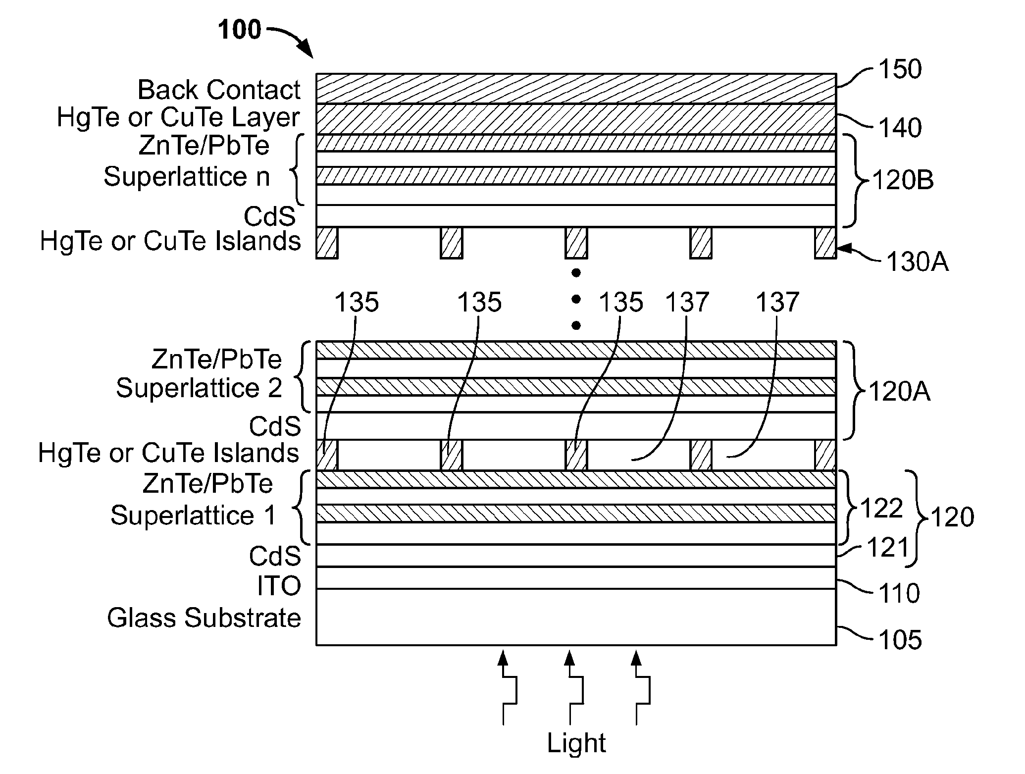
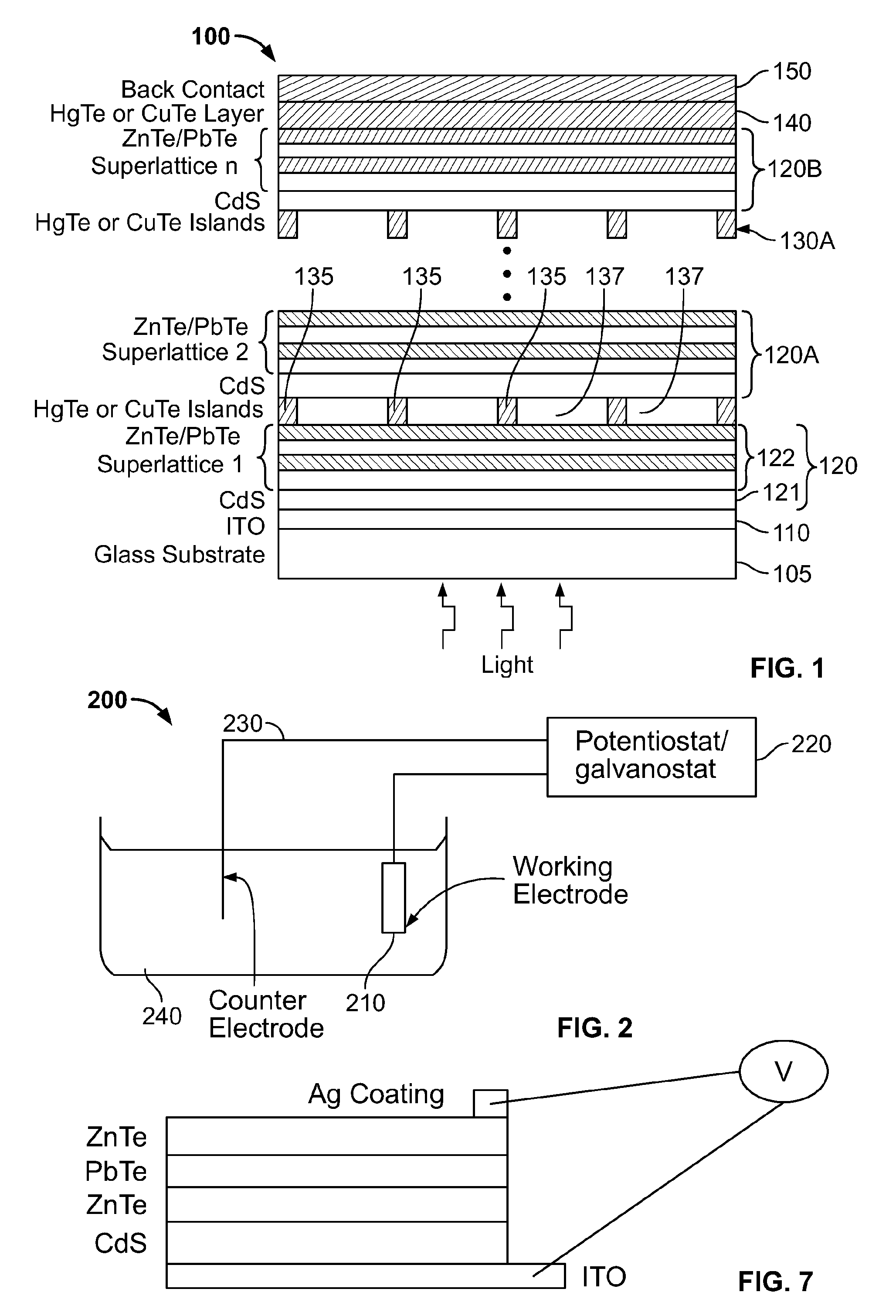
[0006]A multi junction photovoltaic cell includes at least two P-N junctions electrically connected to each other in series. Each P-N junction includes a P-type absorber layer and a N-type emitter layer, each P-type absorber layer including a plurality of alternating thin film layers of zinc telluride and lead telluride, wherein zinc telluride and lead telluride have respective bandgaps when in bulk thickness and the effective bandgap of each P-type absorber layer is between the respective bandgaps, The effective bandgap of at least one P-type absorber layer is different from that of at least one other P-type absorber layer.

Problems solved by technology

These techniques tend to be expensive and involve the use of very toxic chemicals, at least in the case of MOCVD.

Method used


Image

  • Solar cells and method of making solar cells
  • Solar cells and method of making solar cells
  • Solar cells and method of making solar cells

Examples


Embodiment Construction

[0018]This description of the exemplary embodiments is intended to be read in connection with the accompanying drawings, which are to be considered part of the entire written description. In the description, relative terms such as “lower,”“upper,”“horizontal,”“vertical,”“above,”“below,”“up,”“down,”“top” and “bottom” as well as derivative thereof (e.g., “horizontally,”“downwardly,”“upwardly,” etc.) should be construed to refer to the orientation as then described or as shown in the drawing under discussion. These relative terms are for convenience of description and do not require that the apparatus be constructed or operated in a particular orientation. Terms concerning attachments, coupling and the like, such as “connected” and “interconnected,” refer to a relationship wherein structures are secured or attached to one another either directly or indirectly through intervening structures, as well as both movable or rigid attachments or relationships, unless expressly described otherw...


PUM


Abstract

A multi junction photovoltaic cell includes at least two P-N junctions electrically connected to each other in series. Each P-N junction includes a P-type absorber layer and a N-type emitter layer, each P-type absorber layer including a plurality of alternating thin film layers of zinc telluride and lead telluride, wherein zinc telluride and lead telluride have respective bandgaps when in bulk thickness and the effective bandgap of each P-type absorber layer is between the respective bandgaps, The effective bandgap of at least one P-type absorber layer is different from that of at least one other P-type absorber layer.

Description

CROSS-REFERENCE TO RELATED APPLICATIONS[0001]This application claims priority to U.S. Provisional Patent Application No. 61 / 052,298, entitled “Electrodeposition and Characterization of Very Thin Film II-VI Compounds for Novel Superlattice Solar Cells,” filed May 12, 2008, the entirety of which is hereby incorporated by reference herein.FIELD OF THE INVENTION[0002]The present invention relates to thin film solar cells and to solar cells utilizing superlattice structures.BACKGROUND OF THE INVENTION[0003]Solar cells are devices that convert solar energy into electrical energy by releasing electric charges that can move in the semiconductor and ultimately flow through an electric load. The phenomenon of producing current in this way is called the photovoltaic effect. Photovoltaic systems are designed around photovoltaic cells. Since a typical photovoltaic cell produces less than 3 watts at approximately 0.5 volt DC, cells must be connected in series-parallel configurations to produce en...

Claims


Application Information

Patent Timeline
Patent Type & Authority Applications(United States)
IPC IPC(8): H01L31/042H01L31/02H01L31/0264H01L31/18
CPCB82Y20/00H01L21/02557H01L21/02562H01L21/02568H01L21/02628Y02E10/544H01L31/1836H01L31/0725H01L31/073Y02E10/543H01L31/035236
Inventor SINGH, PRITPAL
Owner VILLANOVA UNIVERSITY
Learn More