Bump stopper and manufacturing method therefor

a technology of a stopper and a manufacturing method, which is applied in the direction of shock absorbers, other domestic articles, transportation and packaging, etc., can solve the problems of difficult to maintain constant riding comfort or operation (travel) stability, and achieve excellent material yield rate and manufacturing efficiency, maintain shock-absorbing characteristics and durability performance, and constant dimensional precision

Inactive Publication Date: 2011-06-30
FUKOKU CO LTD
View PDF2 Cites 24 Cited by
  • Summary
  • Abstract
  • Description
  • Claims
  • Application Information

AI Technical Summary

Benefits of technology

[0040]According to the invention, it is possible to provide a bump stopper and a manufacturing method therefor which can constantly maintain the shock-absorbing characteristics and durability performance for a prolonged period of time regardless of the temperature or humidity of the usage environment, which can maintain a constant dimensional precision for a finished product, which is excellent in material yield rate and manufacturing efficiency, and which is low-cost, lightweight, recyclable, and ecological.
[0041]Additionally, it is possible to provide a bump stopper and a manufacturing method therefor which can improve manufacturing efficiency, is excellent in water resistance, and can prevent entry of foreign matter, such as dust into a cylinder body, without providing a dust cover separately.
[0042]Moreover, it is possible to provide a bump stopper and a manufacturing method therefor which can prevent wobbling with respect to a stroke direction of a shock absorber at the time of elastic deformation, thereby maintaining shock-absorbing characteristics in a desired stroke direction.

Problems solved by technology

Then, there is a concern that it may become difficult to maintain a constant riding comfort or operation (travel) stability during traveling.

Method used


Image

  • Bump stopper and manufacturing method therefor
  • Bump stopper and manufacturing method therefor
  • Bump stopper and manufacturing method therefor

Examples


embodiment 1

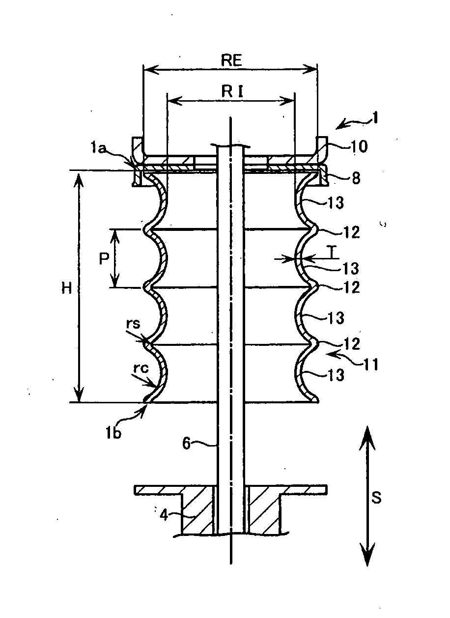
[0118]Since a bump stopper 1 according to Embodiment 1 of the invention, as shown in FIGS. 1A and 1B, is used so as to be provided coaxially with a piston rod 6 of a shock absorber instead of the conventional bump stopper 2 (refer to FIG. 13), the constituent elements of the shock absorber are designated using the same reference numerals as the constituent elements shown in FIG. 13, and thereby a description thereof is omitted. In addition, the bump stopper 1 may not necessarily be provided coaxially with the piston rod 6 of the shock absorber, and its attachment mode is arbitrary.

[0119]The bump stopper 1 includes a hollow cylindrical bellows part 11 which extends along a stroke direction S of the shock absorber and which functions as a shock-absorbing portion.

[0120]The bellows part 11 is constructed such that parts 12 (hereinafter referred to as “first parts 12”) which are molded by thinning thermoplastic resin and are bulged in a direction (radiation direction) opposite to the cen...

embodiment 2

[0160]Next, the bump stopper 101 related to Embodiment 2 will be described with reference to the accompanying drawings.

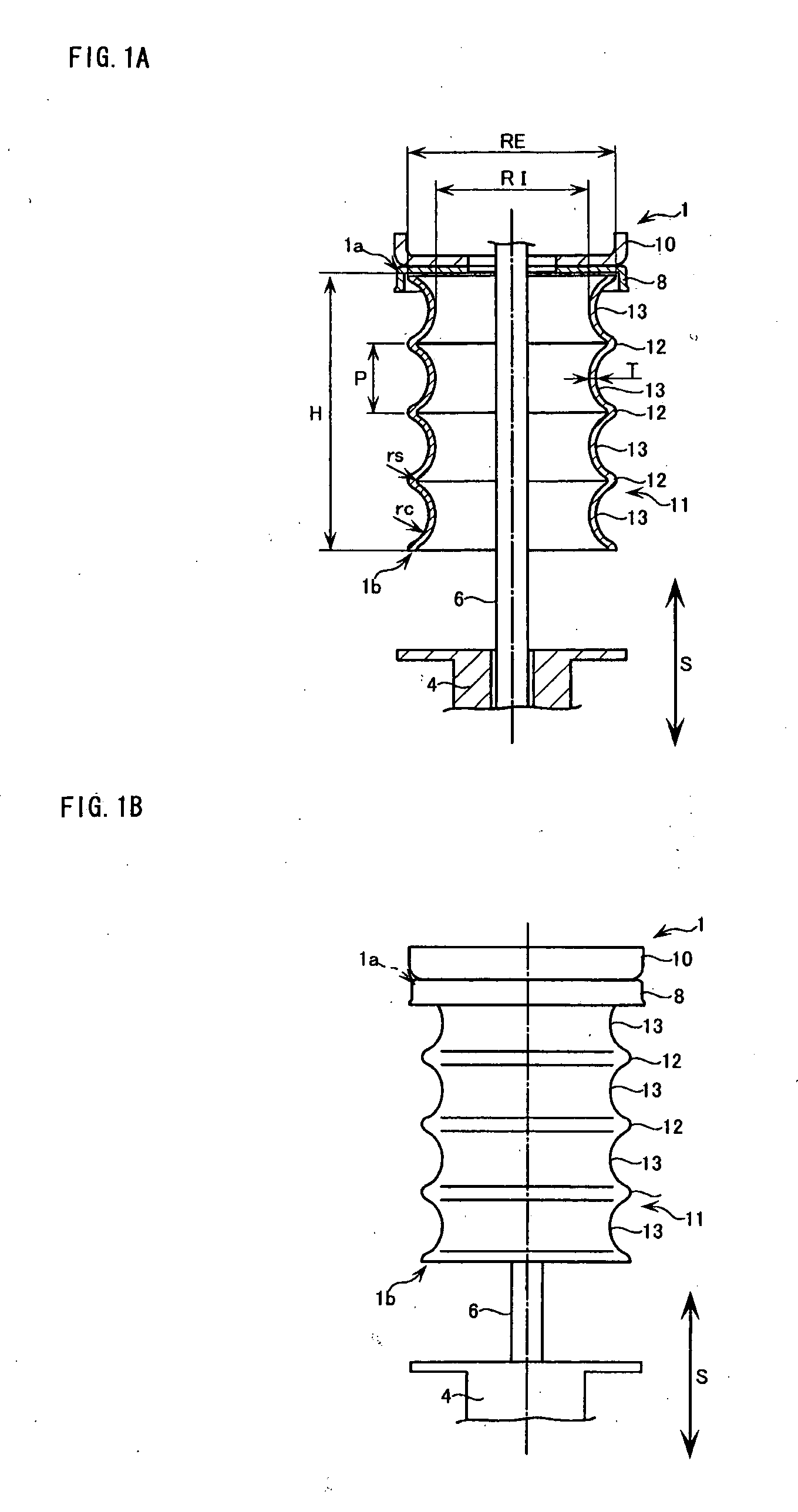
[0161]As shown in FIGS. 4A and 4B, since a bump stopper 101 according to the present embodiment is used so as to be provided coaxially with a piston rod 6 of a shock absorber instead of the conventional bump stopper 2 (refer to FIG. 13); the constituent elements of the shock absorber are designated using the same reference numerals as the constituent elements shown in FIG. 13, and thereby the description thereof is omitted.

[0162]The bump stopper 101 of the present embodiment, as shown in FIGS. 4A and 4B, includes a hollow cylindrical bellows part 111 which extends along the stroke direction S of the shock absorber and which is elastically expandable and contractible along the stroke direction S.

[0163]More specifically, the bellows part 111 is constructed such that first parts 112 which are molded by thinning thermoplastic resin and are bulged in a direction (radiati...

embodiment 3

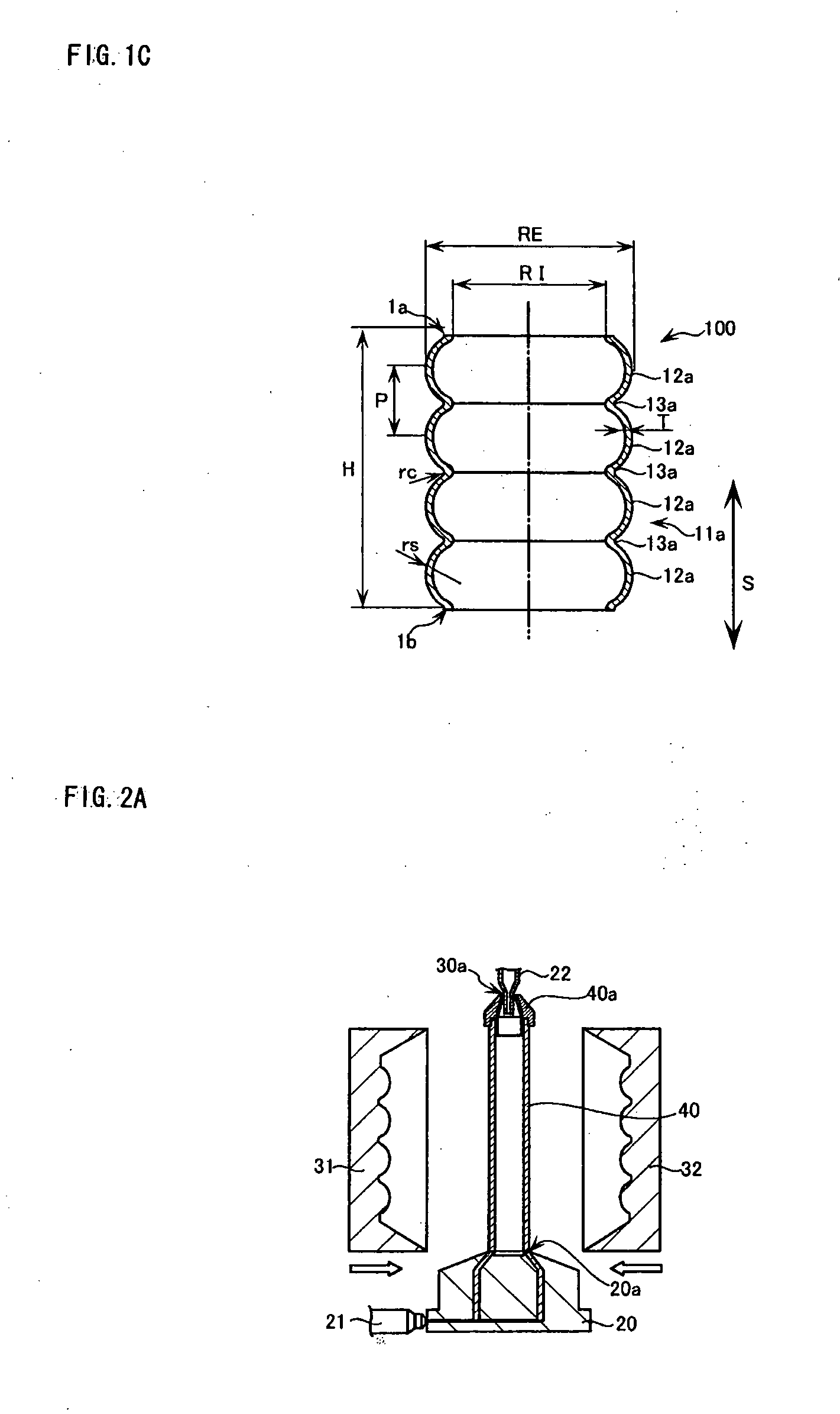
[0215]In Embodiment 2 described above, the case where the axial deviation regulating portion 115 is formed in a cylindrical shape which has a constant internal diameter RM and has a constant external diameter RN with a smaller diameter than the internal diameter RI of the second parts has been described. However, the external diameter RN of the axial deviation regulating portion 115 does not need to be formed with a smaller diameter than the internal diameter RI of the second parts 113.

[0216]For example, one axial deviation regulating portion 115a of the bump stopper 1 of Embodiment 3, as shown in FIGS. 6A and 6B, is disposed at one end in the stroke direction S, i.e., at one end 101b of the bellows part 111 located at the cylindrical body portion 4 side of the shock absorber, and is bonded such that the external diameter RN set to have the same diameter as the external diameter dimensions RE of the most bulged portions of the first parts 112 becomes continuous integrally with the f...


PUM

PropertyMeasurementUnit
radius of curvatureaaaaaaaaaa
diameteraaaaaaaaaa
pressureaaaaaaaaaa

Abstract

Disclosed are a bump stopper and a manufacturing method therefor which can maintain the shock-absorbing characteristics and durability performance constantly for a prolonged period of time regardless of the temperature or humidity of the usage environment, which can maintain a constant dimensional precision for a finished product, which is excellent in material yield rate and manufacturing efficiency, and which is low-cost, lightweight, recyclable, and ecological. A bump stopper (1) is provided in the vicinity of a rod of a shock absorber to elastically limit the stroke of the shock absorber at the time of the contraction thereof and to absorb the shock generated at that time. The bump stopper includes a hollow cylindrical bellows part (11) which extends along a stroke direction S of the shock absorber. The bellows part is formed by thinning thermoplastic resin and is constructed such that first parts (12) which are bulged outward and second parts (13) which are recessed inward are provided alternately and repeatedly in the stroke direction S.

Description

TECHNICAL FIELD[0001]The present invention relates to, for example, a piston rod of a shock absorber which absorbs the shock from the road surface, a bump stopper which is provided in the vicinity of the piston rod to elastically limit the stroke (retraction amount) of the shock absorber at the time of the contraction thereof and to absorb the shock generated at the time of striking bottom (bump touch), and a manufacturing method therefor.[0002]In addition, although the bump stopper may be called, for example, a bump rubber, a jounce bumper, or the like, the bump stopper will be used as a generic term for all of these.BACKGROUND ART[0003]Conventionally, various shock absorbers are used for the suspension for use in, for example, vehicles, such as an automobile, in order to achieve riding comfort or operation (travel) stability during traveling. For example, as shown in Patent Citation 1, the shock absorber includes a cylindrical body portion, and a piston rod supported on the body p...

Claims


Application Information

Patent Timeline
Patent Type & Authority Applications(United States)
IPC IPC(8): F16F1/373F16F1/377B29C49/00
CPCB60G7/04B60G15/062B60G11/22F16F1/373F16F9/58B60G2204/4502B60G15/06B60G2202/143B60G2206/42B60G2206/81012B60G2206/82
Inventor NOBUSUE, KENJIYAMADA, TATSUO
Owner FUKOKU CO LTD
Why Eureka
Try Eureka