Electric power steering device

a technology of electric power steering and steering device, which is applied in the direction of motor/generator/converter stopper, dynamo-electric converter control, instruments, etc., can solve the problems of increasing manufacturing cost, increasing the number of parts in not being aware of the failure of the power steering device, so as to reduce the driving force of the motor

Active Publication Date: 2011-06-30
DENSO CORP
View PDF10 Cites 66 Cited by
  • Summary
  • Abstract
  • Description
  • Claims
  • Application Information

AI Technical Summary

Benefits of technology

[0014]Since the second current to be supplied from the electric power converter to the corresponding winding is reduced when the failure detection element detects the failure of the electric power converter or the winding, the driving force of the motor is reduced. Accordingly, the steering force of the driver is changed, so that the driver is aware of occurrence of the failure. Thus, the steering device can assist the steering force of the driver safety and continuously even if the electric power converter or the winding is failed.

Problems solved by technology

Thus, the driver is not aware of the failure of the power steering device.
When the relay is formed in the electronic power steering device for driving the motor with using a N-system driving circuit, the number of relays to be necessary is three multiplied by N. Accordingly, the number of parts in the power steering device increases, and the manufacturing cost increases.
Thus, the driver may feel anxiety.

Method used


Image

  • Electric power steering device
  • Electric power steering device
  • Electric power steering device

Examples


first embodiment

[0025]An electronic power steering device 1 according to a first embodiment is shown in FIGS. 1 to 4.

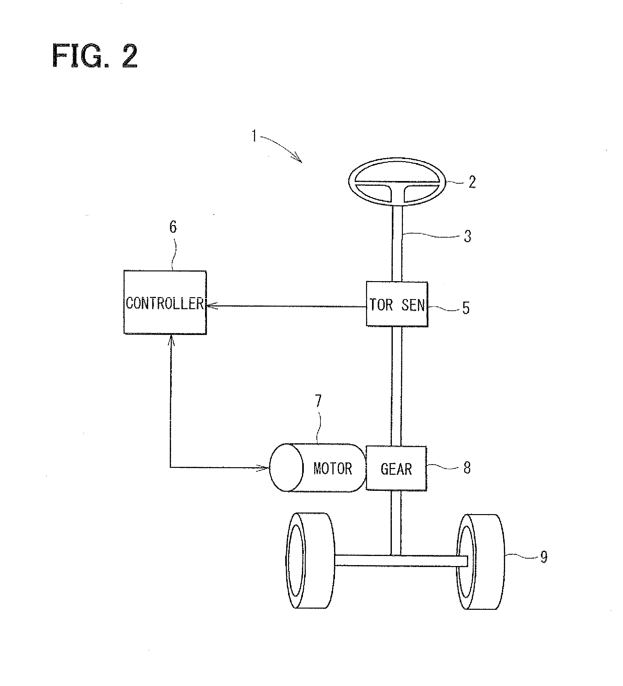
[0026]A construction of the power steering device 1 is shown in FIG. 2. A steering shaft 3 is coupled with a steering wheel 2, which is operated by a driver of a vehicle. A torque sensor 5 detects a steering torque, which is applied to the steering shaft 3.

[0027]A controller 6 for controlling an electronic motor as a control means determines a rotation direction and a driving force of an electronic motor 7 based on a steering torque signal output from the torque sensor 5, a rotational position detection signal of the motor 7, and a vehicle speed signal transmitted via a CAN (controller area network) communication system. Further, the controller 6 sets a current setting instruction signal for outputting the determined rotation direction and the determined driving force.

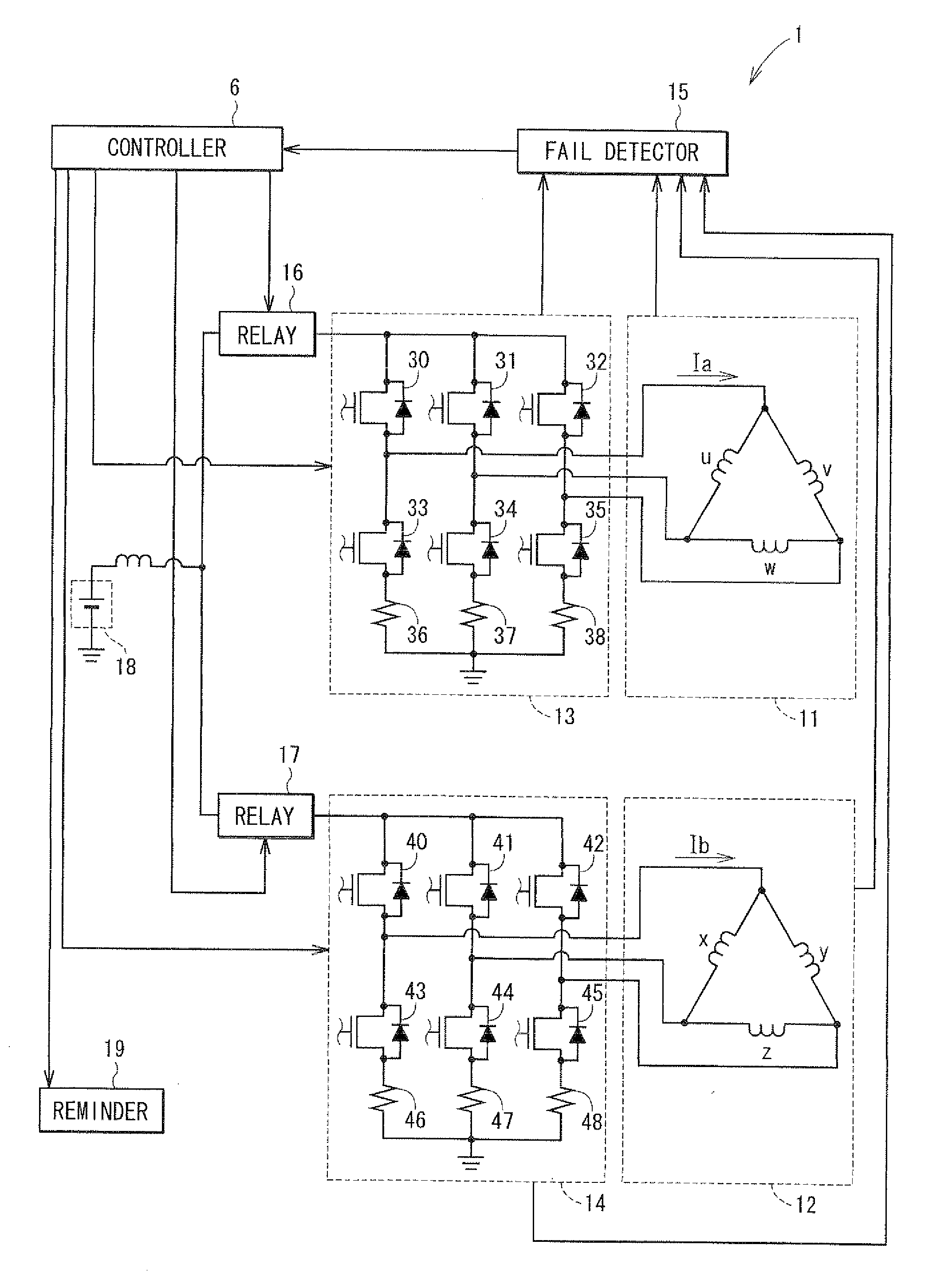
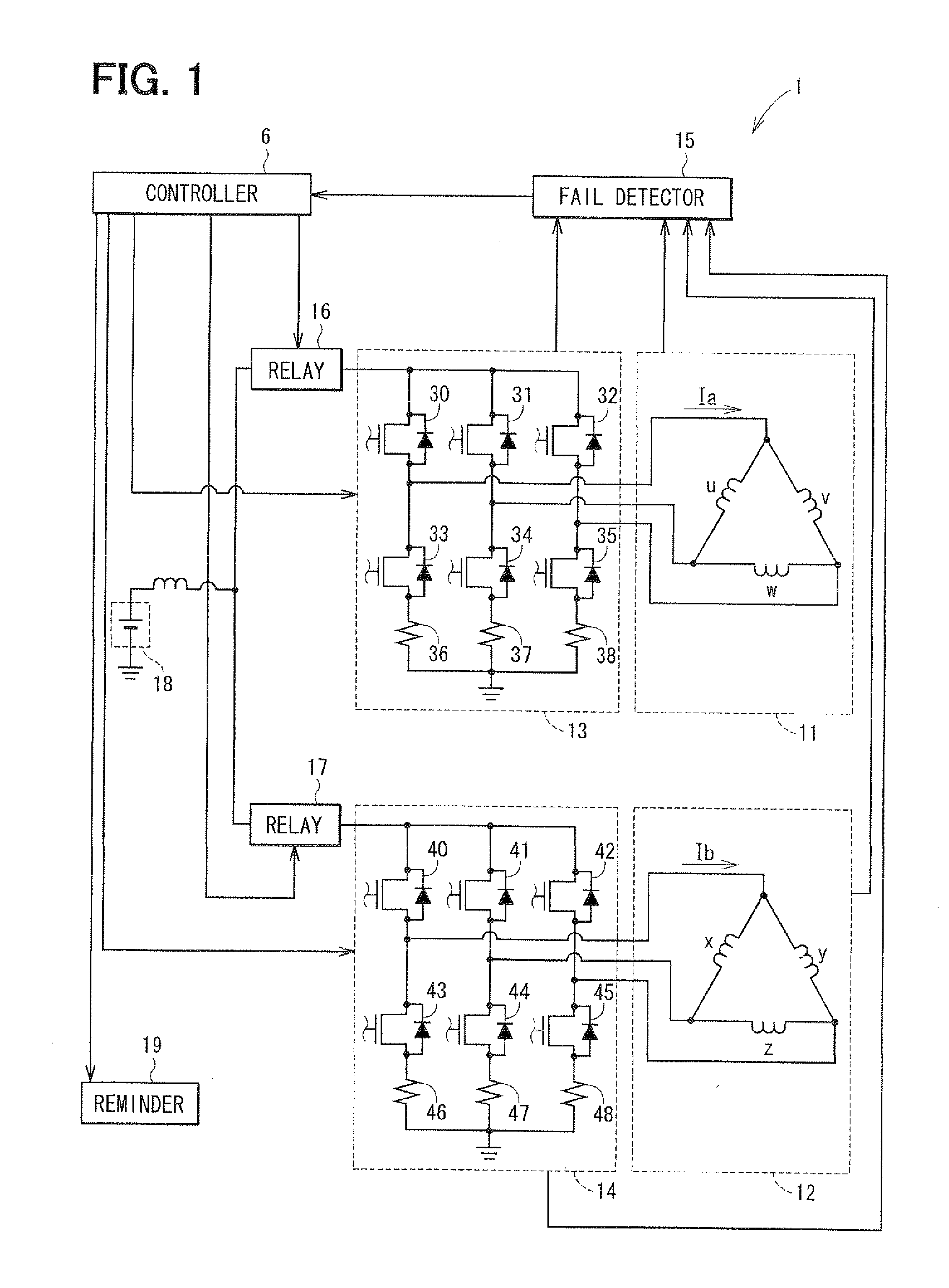
[0028]When the current corresponding to the current setting instruction signal set by the controller 6 is supplied fr...

second embodiment

[0070]The arrangement of the windings of the motor in the power steering device according to a second embodiment is shown in FIG. 5. Each phase winding is winded around a protrusion pole of the stator 73 in such a manner that the mechanical phase difference is the same in a circumferential direction. Specifically, shown as a dotted line Q in FIG. 5, a U-phase winding, a V-phase winding and a W-phase winding in one driving system have the mechanical phase difference of 120 degrees. Further, shown as another dotted line R, a X-phase winding, a Y-phase winding and a Z-phase winding in the other driving system have the mechanical phase difference of 120 degrees.

[0071]In the present embodiment, if the inverter and / or the three-phase windings in one system is failed, and the other system drives the motor, the electro-magnetic attractive force between the stator 73 and the rotor 41 is uniformed in the rotating direction of the rotor 74. Thus, the vibration of the motor is reduced. Accordin...

third embodiment

[0072]An electronic power steering device according to a third embodiment is shown in FIG. 6.

[0073]The motor in the device in FIG. 6 is a brush motor. The brush motor includes two pairs of the windings 51, 52 in the rotor. Current Ia, Ib is supplied from one H-bridge circuit 53, 54 as an electric power converter to a corresponding windings 51, 52.

[0074]Here, two pairs of the windings 51, 52 are arranged symmetrically to a virtual plane including the rotation axis of the rotor. Alternatively, each phase winding in the windings 51, 52 may be arranged such that the mechanical phase difference is the same in the circumferential direction.

[0075]The operation of the steering device in the present embodiment in case of failure is shown in FIG. 7. The operation in FIG. 7 is substantially similar to the first embodiment.

[0076]In the present embodiment, the temperature increase of the switching elements 60-63, 70-73 in the H-bridge circuits 53, 54 and the electric elements is restricted, and ...


PUM


Abstract

An electric power steering device includes: an electric power source for supplying first current; a controller for setting a current instruction value; multiple electric power converters for converting the first current to second current corresponding to the current instruction value; multiple pairs of windings for generating a driving force of a motor; and a failure detection element for detecting failure of the electric power converters and the windings. The controller reduces the current instruction value to be equal to or smaller than a predetermined instruction value of a normal operation when the failure detection element detects the failure. The controller controls the electric power converter in a normal state to supply the second current to a corresponding winding.

Description

CROSS REFERENCE TO RELATED APPLICATION[0001]This application is based on Japanese Patent Application No. 2009-295533 filed on Dec. 25, 2009, the disclosure of which is incorporated herein by reference.FIELD OF THE INVENTION[0002]The present invention relates to an electronic power steering device for driving an electronic motor with a driving circuit having multi-system.BACKGROUND OF THE INVENTION[0003]Conventionally, an electronic power steering device for assisting a steering force of a driver with using a driving force of an electronic motor is well known. The steering device includes various fail-safe functions.[0004]JP-A-2005-304119 teaches that the electronic motor includes multiple three-phase windings. An inverter for supplying current to the windings corresponds to the windings in each set. When a certain inverter or a certain windings in one set is broken, an open / close element stops supplying current from a broken inverter to corresponding windings. Thus, only a normal in...

Claims


Application Information

Patent Timeline
Patent Type & Authority Applications(United States)
IPC IPC(8): H02H3/04H02H7/08
CPCB62D5/0487B62D5/0484
Inventor SATOU, TAKAFUMIURYU, NOBUHIKOMUKAI, YASUHIKO
Owner DENSO CORP
Why Eureka
Try Eureka