Calibration method for a microresistivity logging tool
a microresistivity and logging technology, applied in the field of calibration methods for microresistivity logging, can solve the problems of reducing the sensitivity of the sensor to changes in formation resistivity, introducing an absolute error into the measured formation resistivity, etc., to improve the accuracy and sensitivity of formation resistivity, high resistivity, and high resistivity
- Summary
- Abstract
- Description
- Claims
- Application Information
AI Technical Summary
Benefits of technology
Problems solved by technology
Method used
Image
Examples
embodiment 150
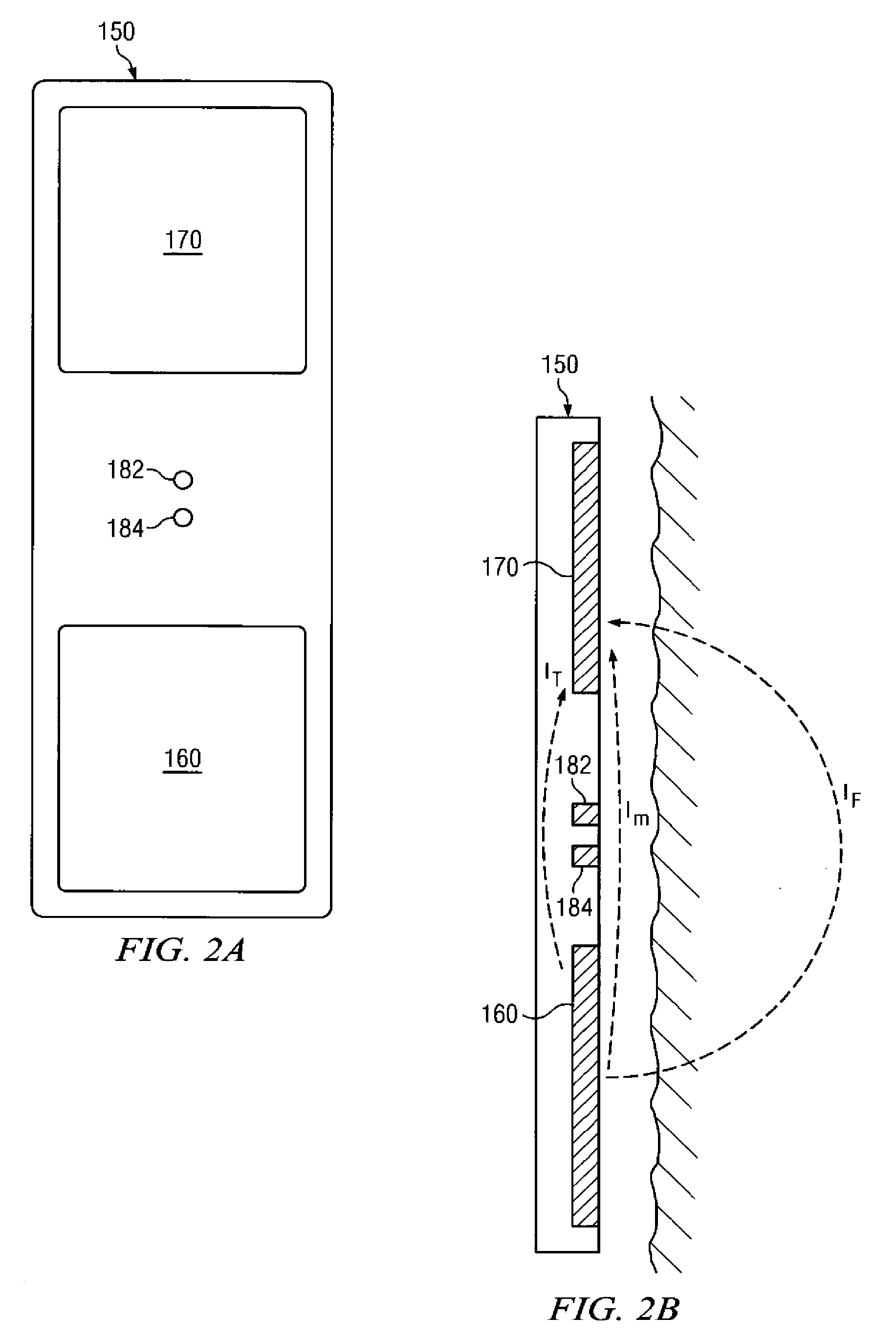
[0024]FIG. 2A depicts a prior art microresistivity sensor embodiment 150 that is suitable for use with the present invention. Sensor 150 includes a conventional four terminal configuration including first and second potential electrodes 182 and 184 deployed between a current injection electrode 160 and a return electrode 170. In use an alternating electrical current is applied between the current injection 160 and return 170 electrodes. The measured potential difference between the potential electrodes 182 and 184 is commonly used to evaluate the formation resistivity.
[0025]It will be understood that the invention is not limited to the use of sensor embodiments including a dipole current injection electrode such as depicted on FIG. 2A. The invention may also make use of microresistivity sensor embodiments including a monopole current injection electrode. Sensor embodiments including a monopole current injection electrode are disclosed in commonly assigned and invented, co-pending U....
embodiment 300
[0030]Turning now to FIG. 4, a flow chart of one exemplary method embodiment 300 in accordance with the present invention is depicted. Method 300 may be thought of as a method for calibrating a four terminal sensor (e.g., sensor 150 depicted on FIGS. 2A and 2B) to accommodate the above described displacement currents. Method 300 is therefore described with further reference to FIGS. 2A and 2B, however, it will be understood that the invention is in no way limited to the rudimentary four terminal sensor embodiment depicted therein.
[0031]At 302 a microresistivity logging tool is deployed in a nonconductive medium, such as air. In one exemplary embodiment the logging tool includes a logging sensor including at least first and second potential electrodes deployed between at least one current injection electrode and at least one return electrode (e.g., as depicted on FIGS. 2A and 2B). At 304 a first high frequency alternating current is applied between the current injection electrode 260...
embodiment 400
[0039]FIG. 6 depicts a flow chart of another exemplary method embodiment 400 in accordance with the present invention. Method 400 may be thought of as another calibration method for calibrating a four terminal sensor so as to accommodate the above described displacement currents. Method 400 is configured for use with sensor embodiments including at least first, second, and third potential electrodes, for example, exemplary sensor embodiments 250 and 250′ depicted on FIGS. 7A and 7B (which are described in more detail below). Method 400 is therefore described with further reference to FIGS. 7A and 7B, however, it will be understood that the invention is in no way limited to the rudimentary sensor embodiments depicted therein.
[0040]In the method embodiment depicted on FIG. 6 a microresistivity logging tool is deployed in a nonconductive medium such as air at 402. The tool includes a sensor having at least first, second, and third potential electrodes deployed between at least one curr...
PUM
 Abstract
Description
Claims
Application Information
 - R&D
- Intellectual Property
- Life Sciences
- Materials
- Tech Scout
- Unparalleled Data Quality
- Higher Quality Content
- 60% Fewer Hallucinations
Browse by: Latest US Patents, China's latest patents, Technical Efficacy Thesaurus, Application Domain, Technology Topic, Popular Technical Reports.
© 2025 PatSnap. All rights reserved.Legal|Privacy policy|Modern Slavery Act Transparency Statement|Sitemap|About US| Contact US: help@patsnap.com


