Eureka AIR delivers breakthrough ideas for toughest innovation challenges, trusted by R&D personnel around the world.

Mode-locker comprising a graphene, and pulse laser device comprising the same

Inactive Publication Date: 2011-06-30
KOREA INST OF SCI & TECH
View PDF2 Cites 20 Cited by
  • Summary
  • Abstract
  • Description
  • Claims
  • Application Information

AI Technical Summary

Benefits of technology

[0007]A mode-locker including a graphene that is capable of effectively causing a laser to be pulsed is provided. In addition, a laser pulse device including the mode-locker is provided.
[0012]A laser pulse device according to an embodiment of the present invention includes: i) an amplifier that amplifies a laser that is transferred along a laser oscillation loop; ii) a mode-locker that is connected to the amplifier and controls the laser; iii) a polarization controller that is connected to the mode-locker and controls polarization of the laser; iv) a coupler that is connected to the polarization controller and branches the laser; v) an isolator that is connected to the coupler and prevents backflow of the laser; and vi) a fiber that connects the amplifier, the mode-locker, the polarization controller, the coupler, and the isolator with each other. The mode-locker includes a graphene layer that is adapted to form a laser pulse.

Problems solved by technology

It has been reported that a semiconductor manufactured by using silicon faces a limitation point in terms of integration and processing speed.
For example, when a line width of the central processing unit (CPU) is controlled to be not more than 10 nm in order to miniaturize the CPU manufactured using silicon, usefulness of the CPU is radically deteriorated due to distorted electromagnetic characteristics.
Furthermore, when the CPU is manufactured by nanotechnology grafting, the price of the CPU is increased.

Method used


Image

  • Mode-locker comprising a graphene, and pulse laser device comprising the same
  • Mode-locker comprising a graphene, and pulse laser device comprising the same
  • Mode-locker comprising a graphene, and pulse laser device comprising the same

Examples


experiment example

Mode-Locker Manufacturing Experiment

[0065]The mode-locker was manufactured by the above method, using the graphene. Other portions except the above method of manufacturing the mode-locker can be easily understood by those skilled in the art, so a detailed description thereof is omitted.

experiment example 1

[0066]D-shaped fiber was prepared by polishing the cladding of a SMF, and a graphene solution was spray-coated on the polished surface thereof. When the D-shaped fiber was fabricated, the surface of the fiber was polished by using abrasives. The surface of the fiber was polished by using abrasives with sizes of 15 μm, 5 μm, 1 μm, and 0.3 μm in four steps. Therefore, laser scattering loss was controlled to be not more than 1 dB after the surface of the fiber was polished. The fiber was polished in order to enhance the broadening of the evanescent field and to minimize the scattering loss on the surface. The amount of final loss was maintained to be not more than 1 dB by measuring loss during the polishing process.

experiment example 2

[0067]A graphene solution was coated and dried on an end portion of the fiber made of a ferrule by using a spray method. The other end portion of the fiber made of the ferrule was connected thereto by a sleeve. Therefore, the laser directly transmits the graphene layer by sandwiching the coated graphene layer. Transmittance of the graphene layer was maintained at about 85% by spray coating the graphene layer on an end portion of the fiber. A single-mode fiber was used and the ferrule was made of a ceramic.

[0068]FIG. 7 shows a scanning electron microscopy photograph of the graphene layer used in the mode-locker manufactured by the experimental example of the present invention.

[0069]As shown in FIG. 7, wrinkles were formed on the graphene layer. The graphene layer was dried while the wrinkles were present on the graphene layer. Recovery time of the graphene layer was measured to be not more than about 200 fs. This was much shorter than the recovery time of the carbon nanotubes.

[0070]L...


PUM


Abstract

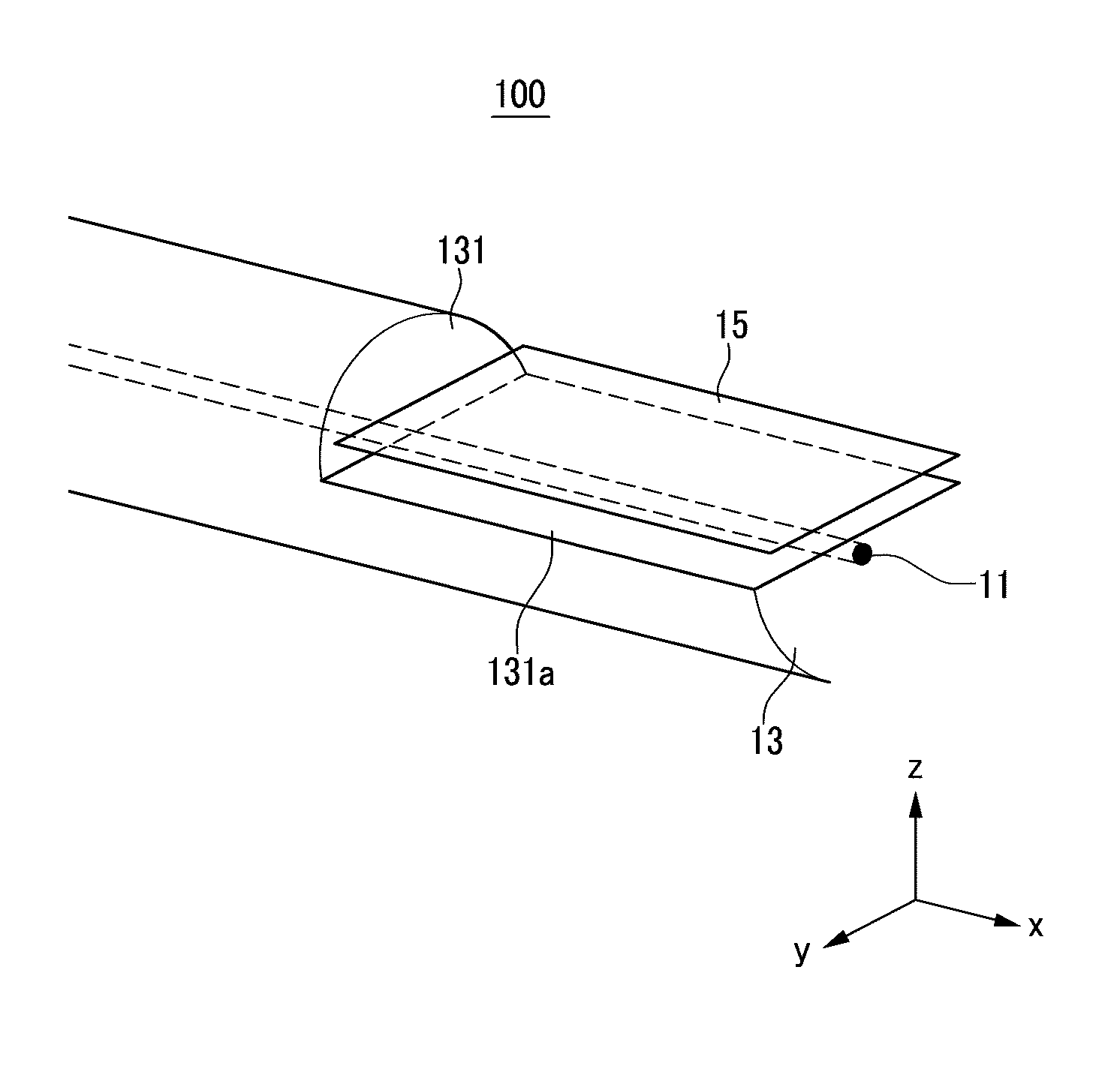
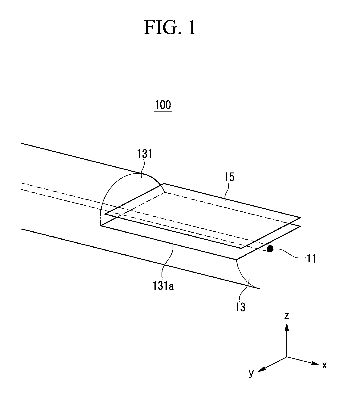
The present invention relates to a mode-locker including a graphene and a laser pulse device. The mode-locker mode-locks a laser that propagates through a laser oscillation loop. The mode-locker includes: i) a core; ii) cladding that surrounds the core, wherein a groove is formed on a side of the cladding; and iii) a graphene layer that is located in the groove and is formed to be extended along a direction to be parallel to a transferring direction of the laser such that a laser pulse is formed by the interaction of the graphene and the field of the propagating laser mode.

Description

CROSS-REFERENCE TO RELATED APPLICATION[0001]This application claims priority to and the benefit of Korean Patent Application No. 10-2009-0133788 filed in the Korean Intellectual Property Office on Dec. 30, 2009, the entire content of which is incorporated herein by reference.BACKGROUND OF THE INVENTION[0002](a) Field of the Invention[0003]The present invention relates to a mode-locker including a graphene, and a laser pulse device. More specifically, the present invention relates to a mode-locker that is capable of effectively mode locking a laser pulse by using the graphene, and a laser pulse device including the same.[0004](b) Description of the Related Art[0005]It has been reported that a semiconductor manufactured by using silicon faces a limitation point in terms of integration and processing speed. For example, when a line width of the central processing unit (CPU) is controlled to be not more than 10 nm in order to miniaturize the CPU manufactured using silicon, usefulness of...

Claims


Application Information

Patent Timeline
IPC IPC(8): H01S3/098
CPCH01S3/08013H01S3/1118H01S3/083H01S3/08054H01S3/00H01S3/10
Inventor SONG, YONG-WON
Owner KOREA INST OF SCI & TECH
Why Eureka
Eureka Blog
Learn More