Method for vision field computing

Active Publication Date: 2011-06-30
TSINGHUA UNIV
View PDF6 Cites 10 Cited by
  • Summary
  • Abstract
  • Description
  • Claims
  • Application Information

AI Technical Summary

Benefits of technology

[0008]The present disclosure is directed to solve at least one of the problems existing in the prior art. Accordingly, a method for vision field computing may be provided, which may realize effective and cost efficient perception and capture for a dynamic scene with high speed using conventional cameras.
[0010]According to some embodiments of the present disclosure, by spatial interleaved sampling, temporal exposure sampling and exposure-variant sampling, using the intrinsic unified consistency between the spatial silhouette projection intersection and the exposure temporal intersection, the effective perception and capture for the dynamic scene with high speed may be achieved with conventional cameras, which is cost efficient and convenient to be put into practice. According to the above embodiments of the present disclosure, without using expensive industrial grade cameras, high-speed dynamic capture for the real 3D scene may also be realized, thereby having very high commercial value with wide applicability.

Problems solved by technology

A conventional video camera with a highest frame rate of about 30 frames per second is used in the above multi-camera systems, which may limit the motion speed of a dynamic scene which may be effectively captured to a large extent.
When the motion velocity of a scene is higher than the highest capture frame rate of the capturing system, motion blur may occur in the captured image.
However, the feature matching may not be performed in the case of motion blur, and consequently effective perception of the dynamic scene may not be realized accordingly.
However, a high-speed camera with a frame rate of above about 500 frames per second is extremely expensive, and the cost of constructing a multi-view high-speed camera capturing system is rendered very high.

Method used


Image

  • Method for vision field computing
  • Method for vision field computing
  • Method for vision field computing

Examples


Embodiment Construction

[0025]Reference will be made in detail to embodiments of the present disclosure. The embodiments described herein with reference to the accompany drawings are explanatory and illustrative, which are used to generally understand the present disclosure. The embodiments shall not be construed to limit the present disclosure. The same or similar elements and the elements having same or similar functions are denoted by like reference numerals throughout the descriptions.

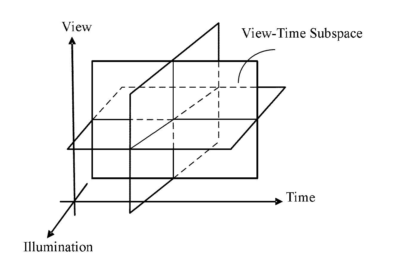
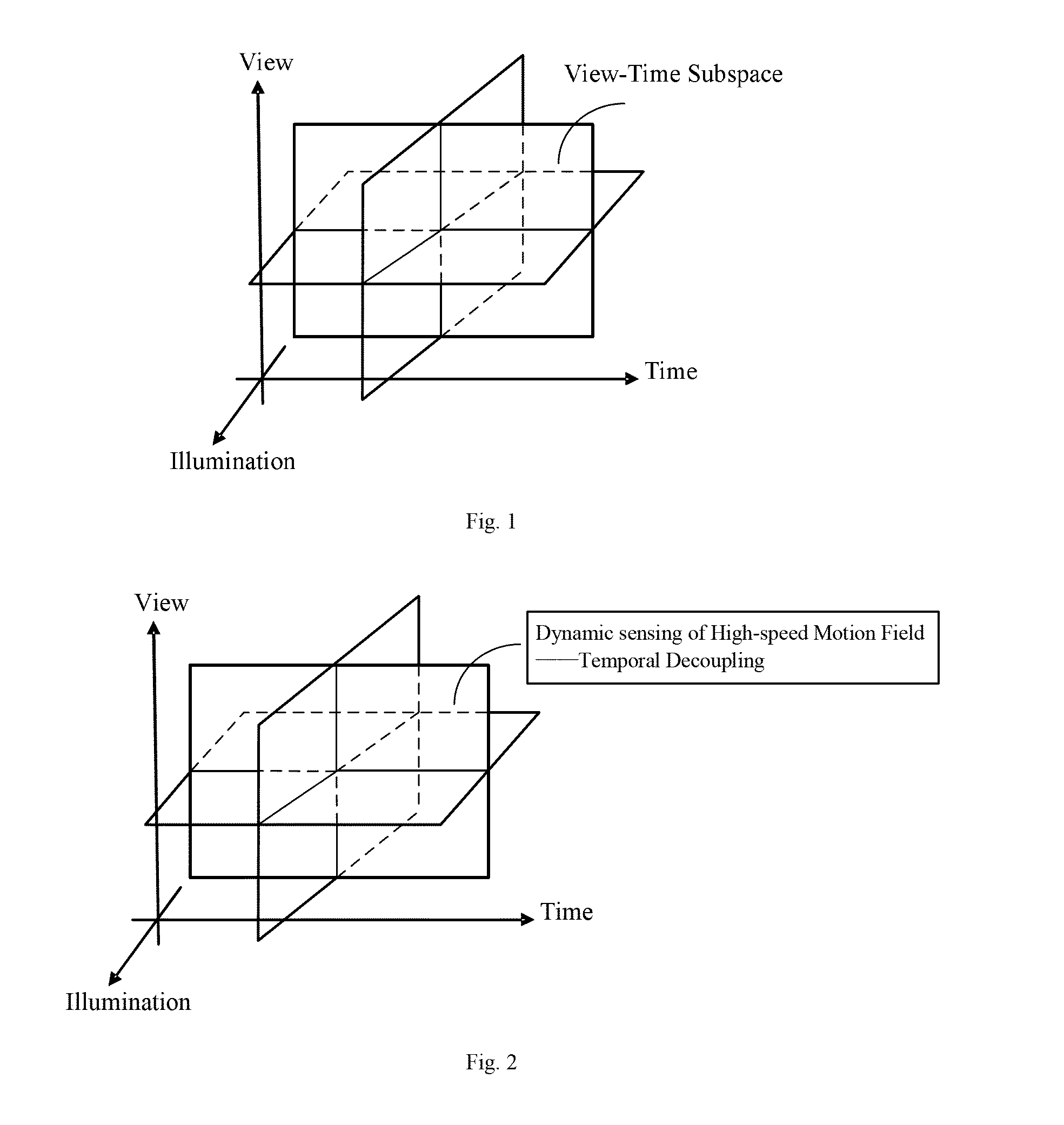
[0026]The inventive concept of the present disclosure may lie in the sampling mechanism of a view-time 2D visual field and a reconstruction framework. And the temporal decoupling concept and method for implementing the same are presented herein for the first time based on intrinsic unified consistency between spatiotemporal intersections. In the following, a method for vision field computing using the inventive concept as proposed hereinbefore will be described in detail.

[0027]The present disclosure is directed to samplin...


PUM


Abstract

A method for vision field computing may comprise the following steps of: forming a sampling system for a multi-view dynamic scene; controlling cameras in the sampling system for the multi-view dynamic scene to perform spatial interleaved sampling, temporal interleaved exposure sampling and exposure-variant sampling; performing spatial intersection to the sampling information in the view subspace of the dynamic scene and temporal intersection to the sampling information in the time subspace of the dynamic scene to reconstruct a dynamic scene geometry model; performing silhouette back projection based on the dynamic scene geometry model to obtain silhouette motion constraints for the view angles of the cameras; performing temporal decoupling for motion de-blurring with the silhouette motion constraints; and reconstructing a dynamic scene 3D model with a resolution larger than nominal resolution of each camera by a 3D reconstructing algorithm.

Description

[0001]This application claims priority to, and benefits of Chinese Patent Application No. 200910243557.7 filed with the State Intellectual Property Office of P.R.C. on Dec. 28, 2009, the entire content of which is incorporated herein by reference.BACKGROUND OF THE DISCLOSURE[0002]1. Field[0003]The present disclosure generally relates to computer vision and graphics visual signal processing, and more particularly to a method for vision field computing.[0004]2. Background[0005]Since the first large-scale camera array system was founded by Kanade at Carnegie Mellon University in 1997, camera array based multi-view dynamic capturing systems and applications thereof have become rapidly developing research focuses in the cross field of computer graphics and computer visioning. Zitnick et al at Microsoft Research has established an 8-camera capturing system and the scene modeling performance with high-quality thereof has been proven. In 2007, Starck at the University of Surrey has establis...

Claims


Application Information

Patent Timeline
IPC IPC(8): G06K9/00
CPCG06T3/0062G06T3/0068G06T5/50G06T7/0065G06T15/205G06T2207/20201G06T2207/10012H04N13/0242H04N13/0282H04N2013/0074G06T5/003G06T2200/08G06T7/55H04N13/243H04N13/282G06T3/12G06T3/14G06T5/73
Inventor DAI, QIONGHAIWU, DILIU, YEBIN
Owner TSINGHUA UNIV
Why Eureka
Try Eureka