Control program, controller, and boiler system

a control program and controller technology, applied in water feed control, instruments, lighting and heating apparatuses, etc., can solve the problems of reducing affecting the desired load follow-up performance, and affecting the efficiency of the boiler, so as to inhibit the loss of start-and-stop, reduce the number of boilers, and increase the efficiency

Active Publication Date: 2011-07-07
MIURA COMPANY LIMITED
View PDF45 Cites 17 Cited by
  • Summary
  • Abstract
  • Description
  • Claims
  • Application Information

AI Technical Summary

Benefits of technology

[0030]In accordance with the boiler system according to the present invention, the intermediate combustion state is assumed to be the high-efficiency combustion position, the combustion quantity in the intermediate combustion state is assumed to be equal to or less than a half of the combustion quantity in the high combustion state, and the combustion quantity in the low combustion state is assumed to be equal to or less than a half of the combustion quantity in the intermediate combustion state, so that if the combustion quantity decreases to a value equal to or less than that in the intermediate combustion state, it can be accommodated by switching the intermedia...

Problems solved by technology

However, in the case of combustion control on a boiler group including a plurality of boilers capable of low combustion and high combustion, if the combustion efficiency during low combustion is higher than that during high combustion, high-efficiency operations can be performed by increasing the number of the combustion-subject boilers based on the low combustion; however, in the case of combustion control based on low combustion, the number of the boilers is decreased as the desired loads decrease, so that start-and-s...

Method used


Image

  • Control program, controller, and boiler system
  • Control program, controller, and boiler system
  • Control program, controller, and boiler system

Examples


Embodiment Construction

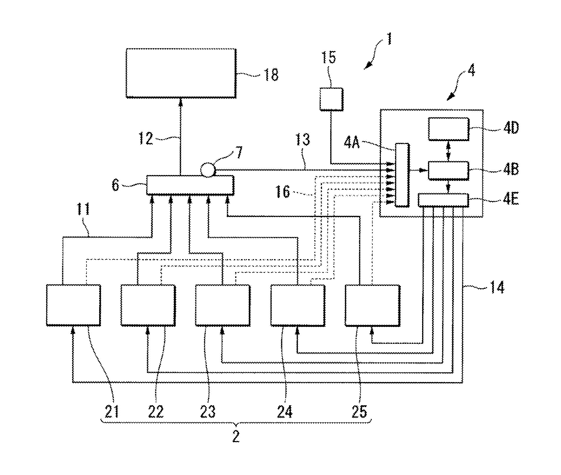
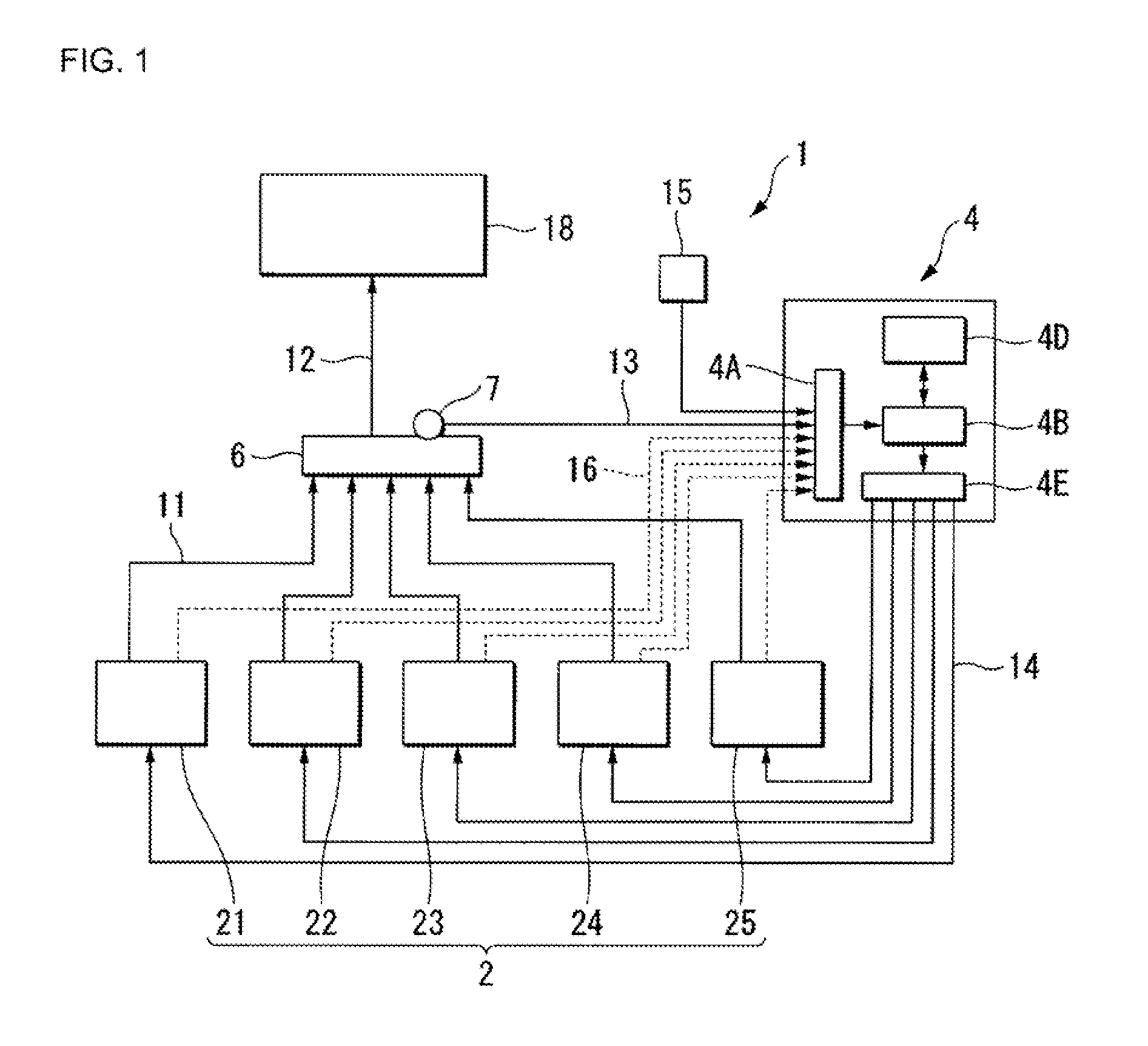
[0037]The following will describe one embodiment of the present invention with reference to FIGS. 1 to 5C. FIG. 1 is a diagram showing the outline of a boiler system according to the present invention, in which reference numeral 1 denotes the boiler system.

[0038]The boiler system 1 includes a boiler group 2 having a plurality of boilers, a control unit 4, a steam header 6, and a pressure sensor 7 mounted on the steam header 6, in which steam generated by the boiler group 2 can be supplied to a steam using installation 18.

[0039]In the present embodiment, a desired load is the quantity of steam dissipated by the steam using installation 18, so that a pressure P of the steam in the steam header 6 to be controlled is detected with the pressure sensor 7 and, based on the pressure P, the control unit 4 conducts control on the quantity of combustion in the boiler group 2.

[0040]The boiler group 2 includes, for example, five steam boilers of a first boiler 21, a second boiler 22, a third boi...


PUM


Abstract

The present invention relates to a control program, a controller, and a boiler system that are related to a boiler group including a plurality of boilers controlled in combustion at stepwise combustion positions. It is well suitable, in a control program for conducting control on a boiler system that includes a boiler group having a plurality of boilers which can be controlled in combustion quantity at stepwise combustion positions and in which at least one of the combustion positions is assumed to be a high-efficiency combustion position and that is configured to be controlled in combustion based on an increase/decrease in desired loads, that in the case of increasing a quantity of combustion in the boiler group, after a high-efficiency combustion shift signal that makes the shift to the high-efficiency combustion position is output to all of the boilers subject to high-efficiency control by which control is conducted on the basis of combustion at the high-efficiency combustion position, a control signal may be output that makes the shift to a higher combustion position than the high-efficiency combustion positions for any one of the high-efficiency control subject boilers.

Description

BACKGROUND OF THE INVENTION[0001]1. Field of the Invention[0002]The present invention relates to a control program, a controller, and a boiler system that are related to a boiler group including a plurality of boilers controlled in combustion at stepwise combustion positions. This Application claims priority based on Japanese Patent Application No. 2008-215676, filed on Aug. 25, 2008, the content of which is hereby incorporated.[0003]2. Description of the Related Art[0004]Conventionally, in the case of bringing a steam pressure or a hot water temperature close to a target value through combustion in a boiler group including a plurality of boilers, control has been conducted widely on the boilers by calculating the number of combustion-subject boilers and their combustion positions based on an increase / decrease in desired load, technologies on which combustion control are disclosed (see, for example, Japanese Patent Application Laid-Open Publication No. 2002-130602).[0005]Further, as...

Claims


Application Information

Patent Timeline
IPC IPC(8): F22D5/00G05B21/00
CPCF22B35/00F22B33/00
Inventor MIURA, KOJI
Owner MIURA COMPANY LIMITED
Why Eureka
Try Eureka