
Reflective energy management system

Active Publication Date: 2011-07-14
SUMNER WALTON
View PDF99 Cites 11 Cited by
  • Summary
  • Abstract
  • Description
  • Claims
  • Application Information

AI Technical Summary

Benefits of technology

[0015]The present invention teaches a combination of four roofing components that collectively provide safe, durable, adaptive rejection of heat in the summer and conservation of heat in the winter. The invention combines reflective surfaces, passive solar construction techniques applied on small scales, and durable clear coatings to create passive solar shingles, the first component of the invention. The second component is a shingle designed to radiate infrared energy from a shaded roof. A preferred embodiment of the invention further combines reflective surfaces, a blind mechanism, and a temperature sensitive mechanism for rotating the blind mechanism to create sub-roof adaptable insulators. A sub-roof adaptable insulator designed to underlie a sunlit roof is the third component of the invention. A sub-roof adaptable insulator designed to underlie a shaded roof is the fourth component of the system.
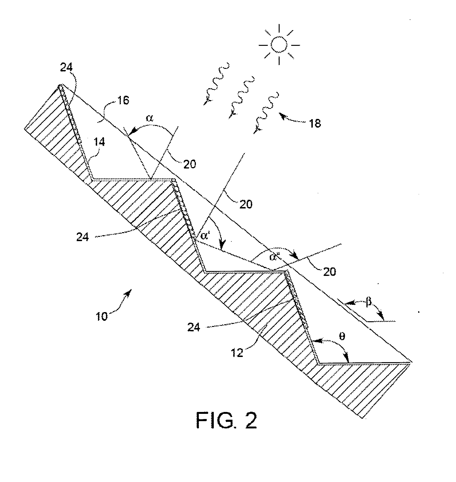
[0017]The passive solar shingles on the sunlit roof channel low angle incident sunlight to energy absorbing areas on the shingle, warming the shingle. The reflection of low angle sunlight at morning and evening is limited by shingle design to avoid blinding ground level observers. If the sub-roof space immediately below a sunlit roof cools below a pre-selected temperature, the sub-roof adaptable insulator for a sunlit roof closes to limit radiant and convective heat losses from the area below the adaptable insulator. Conversely, if the solar-heated shingles heat the sub-roof adaptable insulator sufficiently, then the insulator opens to allow heat exchange with the wider sub-roof area. The sub-roof adaptable insulator for a shaded roof closes to limit radiant and convective loss of heat energy through the shaded roof. This limits heat loss through the radiating shingles on the shaded roof. The radiating shingles may also be inefficient radiators at cold temperatures, further limiting heat loss.

Problems solved by technology

The radiating shingles may also be inefficient radiators at cold temperatures, further limiting heat loss.

Method used


Image

  • Reflective energy management system
  • Reflective energy management system
  • Reflective energy management system

Examples


Embodiment Construction

[0039]The invention will now be described with reference to the drawing figures, in which like reference numerals refer to like parts throughout.

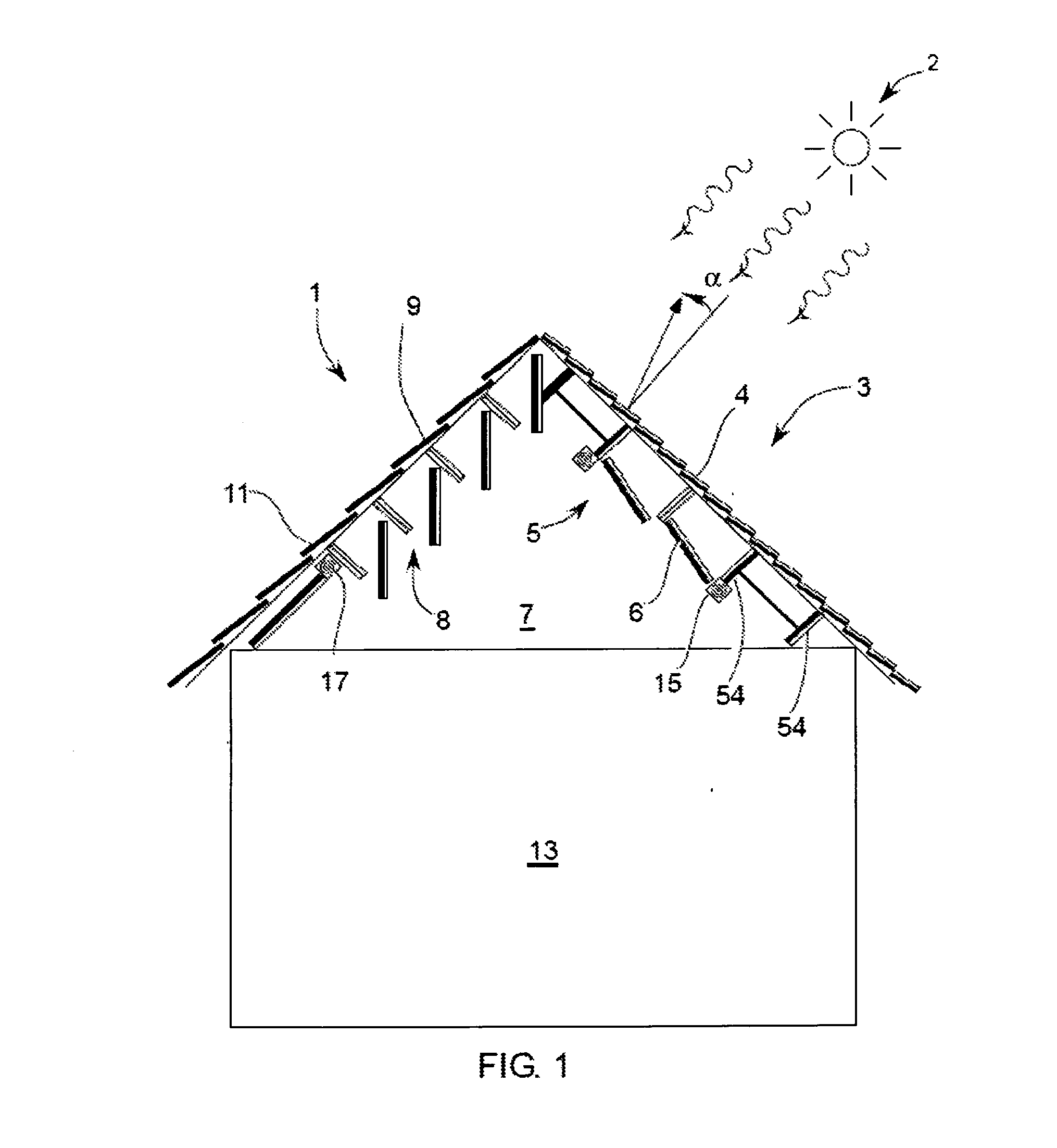
[0040]FIG. 1 illustrates a building 1 equipped with four adaptive passive solar roof features, in configuration for summer sun 2. First, sunlight reflects from the sunlit portion of the roof 3 due to reflective shingles 4. This reduces radiant heat gain significantly. Second, an adaptive insulating layer 5 is present under the sunlit roof 3. The adaptive insulating layer 5 orients panels, or blinds 6 so that a reflective surface generally faces the roof 4 and seals against fixed supports 54 or adjacent blinds 6 to form a nearly solid barrier, restricting convective heat exchange between the sunlit roof 4 and the attic space 7. In cold weather conditions, adaptive insulating layer 5 is operable to open blinds 6 to permit convective heat exchange between roof 3 and attic space 7. Third, a second adaptive insulating layer 8 is present under th...


PUM

PropertyMeasurementUnit
Angleaaaaaaaaaa
Angleaaaaaaaaaa
Temperatureaaaaaaaaaa

Abstract

A four component roofing system uses three reflective subsystems and one radiant subsystem to provide passive temperature control of a building comprising: (1) Shingles that reflect high angle summer sun light back to the sky, but absorb low angle winter sunlight; (2) A temperature sensitive attic insulator placed under a sunlit roof that reflects radiation and blocks convection from the roof to the attic at hot temperatures, permits radiation and convection at warm temperatures, and blocks radiation and convection from the attic at cold temperatures; (3) A temperature sensitive attic insulator placed under a shaded roof that permits radiation and convection at warm or hot temperatures, and blocks radiation and convection from the attic at cold temperatures; (4) Non-reflective shingles on a shaded roof that emit radiation continuously, but that are heated by air and radiation from the attic only when the second temperature sensitive attic insulator permits convection, so that radiant heat loss is reduced at cold temperatures.

Description

CROSS-REFERENCE TO RELATED APPLICATIONS[0001]This application claims priority from U.S. Provisional Application Ser. No. 61 / 095,024 filed on Sep. 8, 2008, which is incorporated herein by reference in its entirety.FIELD OF THE INVENTION[0002]The present invention describes a four component roofing system using three reflective subsystems and one radiant subsystem to provide passive temperature control of a building comprising: (1) Shingles incorporating a passive solar design that reflect high angle summer sun light hack to the sky, but absorb low angle winter sunlight; (2) A first temperature sensitive attic insulator placed under a sunlit roof that reflects radiation and blocks convection from the roof to the attic at hot temperatures, permits radiation and convection at warm temperatures, and blocks radiation and convection from the attic at cold temperatures; (3) A second temperature sensitive attic insulator placed under a shaded roof that permits radiation and convection at war...

Claims


Application Information

Patent Timeline
IPC IPC(8): E04D13/18B32B15/04D06N5/00B32B27/30B32B3/30B32B3/10E04H14/00
CPCE04D1/28Y10T428/24612Y10T428/24322E04D13/1637F24S20/69Y02B10/20Y02E10/40Y10T428/31504Y10T428/31678Y10T428/31935
Inventor SUMNER, WALTON
Owner SUMNER WALTON
Learn More