Turbomachine nacelle and Anti-icing system and method therefor

a technology of anti-icing and nacelle, which is applied in the field of aircraft engine nacelles, can solve the problems of reducing engine efficiency, affecting engine performance, and requiring excessive energy for de-icing and anti-icing operations, so as to remove and prevent ice buildup

Active Publication Date: 2011-07-14
MRA SYST LLC
View PDF8 Cites 25 Cited by
  • Summary
  • Abstract
  • Description
  • Claims
  • Application Information

AI Technical Summary

Benefits of technology

[0010]According to a second aspect of the invention, the above-described construction provides for a method capable of removing and preventing ice buildup on the inlet lip of a nacelle. Such a method entails fabricating the inlet lip to have a cross-sectional shape and oppositely-disposed exterior and interior surfaces, and contacting at least the inlet lip of the nacelle with an anti-icing system comprising at least one heating element having a cross-sectional shape that conforms to the cross-sectional shape of the inlet lip, and within which carbon nanotubes are oriented and arranged to conduct electrical current through the heating element. The method further entails passing an electrical current through the heating element to cause Joule heating of the heating element and heating of the inlet lip by thermal conduction.

Problems solved by technology

The hot air bled from the engine 10 results in a corresponding negative impact on engine performance and detracts from engine efficiency (SFC).
Additionally, hot air bleed systems of the type represented can incur a significant weight penalty.
A drawback of such systems is that they typically require excessive energy for de-icing and continuous anti-icing operation on large aircraft engines, such as high-bypass turbofan engines of the type represented in FIG. 1.
Furthermore, electrical anti-icing systems are relatively heavy and detract from engine efficiency / performance.
Notable disadvantages of weeping systems include the high cost of chemical de-icing agents, the requirement that the aircraft carry the de-icing agent at all times, and the inoperability of the system if the supply of chemical agent is exhausted during flight.
Disadvantages of de-icing boots include the requirement for a pump to inflate the bladders and a relatively short life span.
However, the use of composite materials such as graphite-reinforced epoxy laminates in place of conventional aluminum alloy nacelles and wing structures poses additional challenges to anti-icing systems, since laminate composite materials exhibit relatively poor thermal conductivity in the thickness direction (and therefore between adjacent laminae), reducing the efficiency with which conventional anti-icing systems can heat the outer surfaces of a nacelle to remove and prevent ice buildup.

Method used


Image

  • Turbomachine nacelle and Anti-icing system and method therefor
  • Turbomachine nacelle and Anti-icing system and method therefor
  • Turbomachine nacelle and Anti-icing system and method therefor

Examples


Embodiment Construction

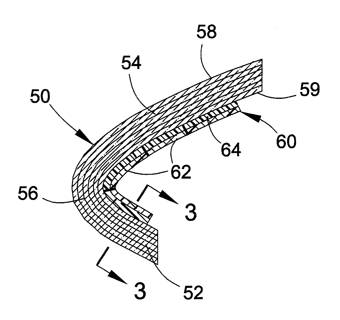
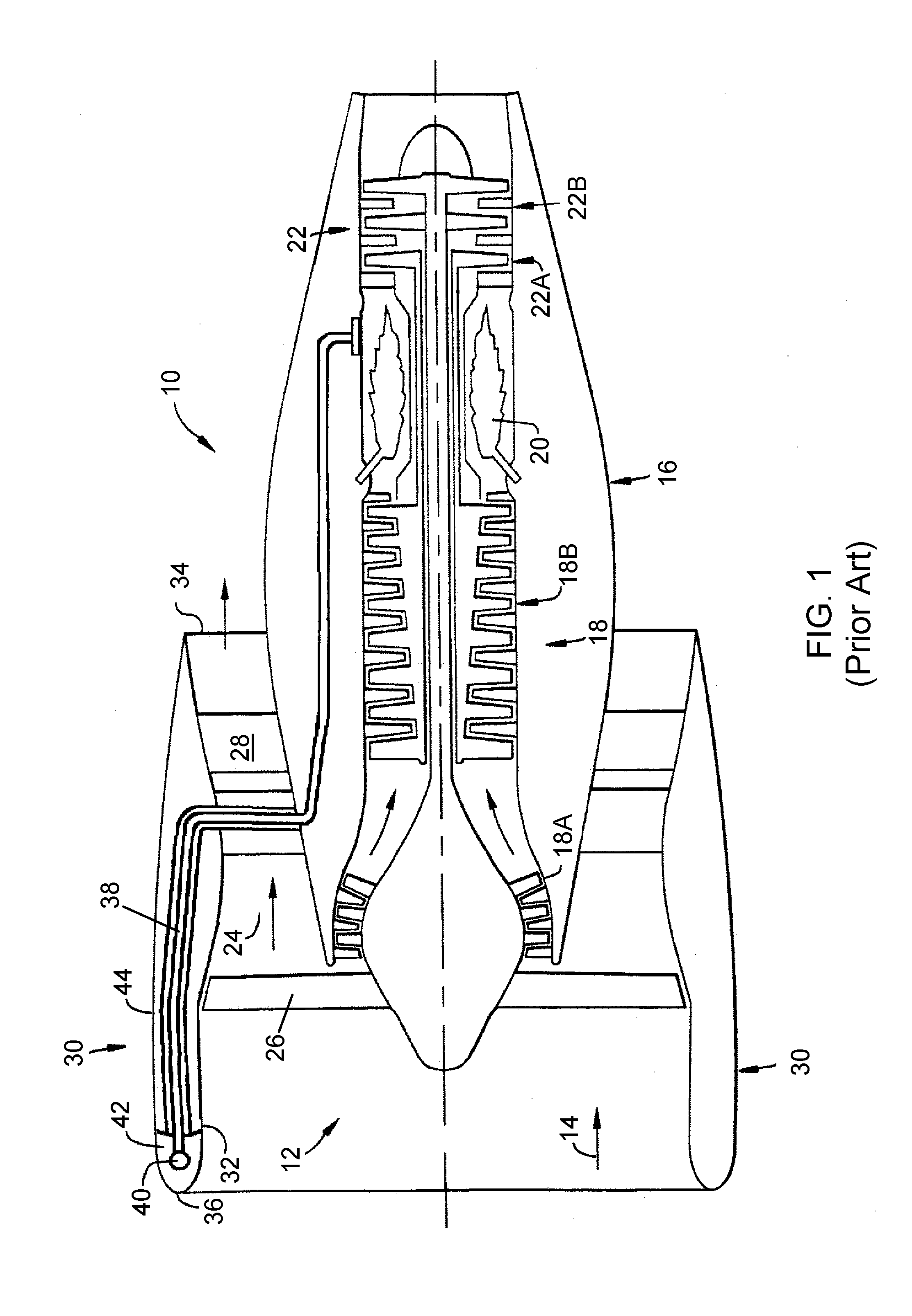
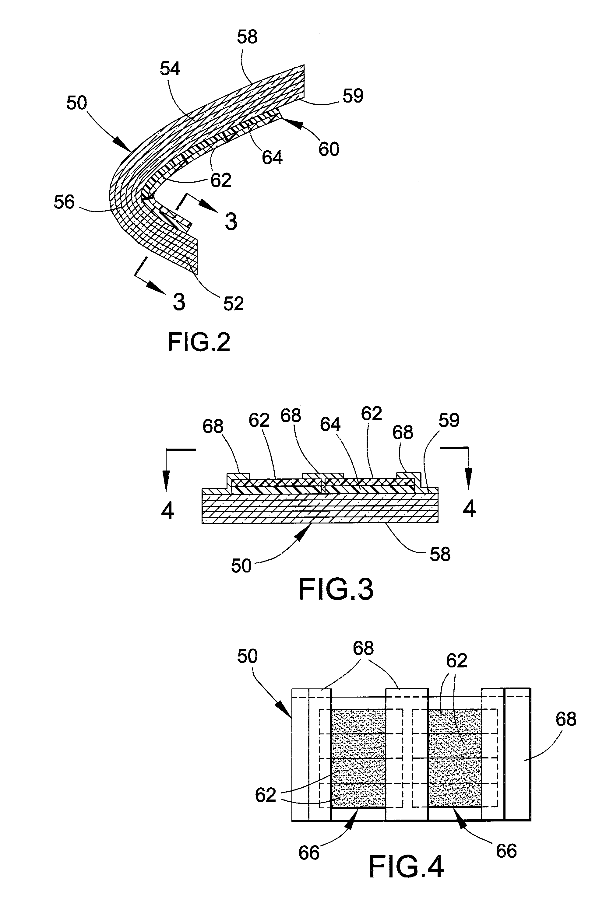
[0019]FIGS. 2 through 6 represent two embodiments of the present invention by which an anti-icing and de-icing capability (hereinafter, simply referred to as anti-icing) is provided in combination with an aircraft engine nacelle 50 or 70, which may be manufactured so that at least its section at the inlet lip is fabricated from a composite material. The invention is particularly well suited for use in a high-bypass turbofan engine, an example of which is the turbofan engine 10 represented in FIG. 1, though it should be understood that other applications are foreseeable. For convenience, the invention will be described with reference to the engine 10 in FIG. 1, though modified to some extent by details of the invention described in reference to the embodiments of FIGS. 2 through 6.

[0020]The nacelles 50 and 70 of FIGS. 2 through 6 can be formed of a variety of materials, including such conventional materials as metal alloys and particularly aluminum alloys. However, a preferred aspect...


PUM

PropertyMeasurementUnit
diametersaaaaaaaaaa
thicknessesaaaaaaaaaa
diametersaaaaaaaaaa

Abstract

An anti-icing system and method for an aircraft engine nacelle. The nacelle has an inlet lip that defines a leading edge of the nacelle and has a cross-sectional shape and oppositely-disposed exterior and interior surfaces. An anti-icing system contacts at least the inlet lip of the nacelle. The anti-icing system includes at least one heating element having a cross-sectional shape that conforms to the cross-sectional shape of the inlet lip and in which carbon nanotubes are oriented and arranged to conduct electrical current through the heating element. Passing an electrical current through the heating element causes Joule heating of the heating element and heating of the inlet lip by thermal conduction.

Description

BACKGROUND OF THE INVENTION[0001]The present invention relates to turbomachinery, and more particularly to anti-icing and de-icing systems for aircraft engine nacelles fabricated at least in part from composite materials.[0002]High-bypass turbofan engines are widely used for high performance aircraft that operate at subsonic speeds. As schematically represented in FIG. 1, a high-bypass turbofan engine 10 includes a large fan 12 placed at the front of the engine 10 to produce greater thrust and reduce specific fuel consumption. The fan 12 serves to compress incoming air 14, a portion of which flows into a core engine (gas turbine) 16 that includes a compressor section 18 containing low and high pressure compressor stages 18A and 18B to further compress the air, a combustion chamber 20 where fuel is mixed with the compressed air and combusted, and a turbine section 22 where a high pressure turbine 22A extracts energy from the combustion gases to drive the high pressure stages 18B of t...

Claims


Application Information

Patent Timeline
Patent Type & Authority Applications(United States)
IPC IPC(8): F02C7/047B82Y30/00
CPCF02C7/047Y02T50/672B64D2033/0233F05D2300/5024B64D15/12F05D2300/224Y02T50/60
Inventor MAHESHWARI, MAHENDRA
Owner MRA SYST LLC
Why Eureka
Try Eureka